TICOM: the TINE based
CANopen Manager
Introduction
TICOM is a TINE server which standardizes the information
flow between the CANopen devices and the higher levels of the TINE control
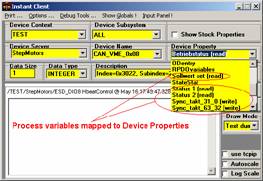
system. All CANopen devices present on the CAN bus are accessible as TINE
devices, and all process variables of CANopen nodes are directly addressed as
TINE properties of the devices. CANopen
specific details (such as bit representation of data and assignment of data to
a CAN message) are hidden at this level. Client applications contacting servers
deal only with the names identifying the data. Such an approach not only frees
the client application programmers from learning the CANopen protocol, but also
makes possible future hardware replacement with other designs for which the
process variables may be represented in another way.
The entire configuration of the TICOM bus interface layer
and the mapping of CANopen data to TINE are accomplished automatically at
start-up by reading in a CANopen DCF (Device Configuration File) or EDS
(Electronic Data Sheet) for each bus node and using the CANopen object
dictionary descriptions to bind memory locations to the bus process variables
and their names.
TICOM also implements partially the functionality of the
CANopen Manager (defined by the DS301 and DS302 CANopen specification),
providing mechanisms for node configuration management, Network Management
Master (NMT), and SYNC and Time message generation.
TICOM is written in C++ and is available now for Linux, but
the port to other operating systems, especially for MS Windows, is being
considered.
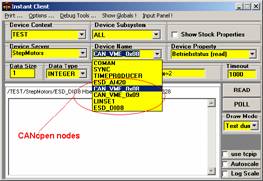
Since TICOM is a TINE server, therefore it can be accessed
by TINE generic client applications, like an Instant Client or Java Tine
Client. In order to provide a more comfortable way of managing the CANopen bus
and nodes, the dedicated TicomViewer client application was written.
Features
Ø
Runs on Linux and
ELINOS embedded Linux distribution, and
presumably on other Unix-like systems
Ø
NMT master
Ø
Heartbeat consumer, when needed node guarding mechanism
automatically activated
Ø
SYNC producer with one COBID = 0x80
Ø
Time producer
Ø
Up to 8 independent bus lines, each up to 127 devices
Ø
Handles up to 8 Transmit PDOs (up to 64 process variables) and 8 Receive PDOs (up to 64 transmitting and
up to 64 receiving process variables )
Ø
One SDO channel for each node, segmented transfer supported.
Ø
Assumes the CANopen predefined message identifiers (CAN in
Automation predefined connection set)
Ø
Automatic configuration of PDOs and process variable mapping,
driven by the EDS/DCF files parsed data
Ø
TINE server, configured via command line parameters rather than
csv or xml files
Ø
Remote control of NMT
master, SYNC and Time producer
Ø
Remote access to nodes’ Object Dictionary: mapping TINE calls to
SDOs
Ø
Process variables of nodes accessible as tine devices’ properties
Ø
Available platform independent (Java) TicomViewer client
application for CANopen diagnostic purposes
CAN bus interfacing hardware
Currently TICOM
can address two families of CAN interfaces
Ø
PEAK (see: www.peak-system.com ):
o
PCAN-ISA PC-ISA I + II CAN-Interface one and two
channel
o
PCAN-PC/104
PC/104 CAN-Interface
one and two channel
o
PCAN-Dongle
PC-Parallel Port
CAN-Interface one channel
o
PCAN-PCI
PC-PCI
CAN-Interface one or two channel
o
PCAN-PCI
Express PC-PCI
Express CAN-Interface one or two channel
o
PCAN-PC
Card PC-PC Card (PCMCIA) CAN-Interface one or two channel
o
PCAN-PC/104plus PC/104plus CAN-Interface one and
two channel
o
PCAN-USB
PC-USB CAN
Interface
o
PCAN-OEM
All OEM-Mainboards
Boards with PEAK-CAN Interface
(DigitalLogic-PC/104
CAN cards, Kontron with CAN
on board, etc)
Ø
ESD (see: www.esd-electronics.com/esd2004/english/index_js.html
)
Installing the TICOM
In order to install TICOM you have to obtain the source files, compile them and link on your machine. The most recent version of the project was built as a Netbeans 6. 5. C++ project. If you are also a Netbeans user you can download the entire project, and just build it on your machine.
If you prefer to download source files only and a related makefile, you can do it here.
Running TICOM
Locations of DCF files
TICOM expects DCF files (DCF = Device Configuration File,
the CANopen device standardized configuration file) copied into its working
directory. TICOM reads these files and
builds a list of devices, which TICOM expects to find on the bus. Other devices
will be ignored: the messages from unlisted devices will be rejected. However,
the bus-wide NMT commands, like a ‘NMT boot-up’ command, will of course affect
all devices present on the bus.
Command Line Options
TICOM can be started with several command line options. In
order to get a list of available options, type ./ticom –h. You should get something
like this:
usage: ticom
[options...]
use csv option exclusively with options
-n, -s
options:
-csv <csv configuartion file
name> : use a CSV configuartion file
-esd :
use an ESD CAN driver rather than a PEAK CAN driver (default)
-n <number> : PEAK
can device number (32 = PCAN_USB, when omitted)
or ESD net number
-d <number> :
run in debug mode with given debug level
-tine.s <name> :
register as TINE server <name>
-tine.p <number> :
use <number> as a port offset for TINE FEC
-tine.f <name> :
use <name> as a TINE FEC name
-tine.c <name> :
use <name> as a TINE FEC context
-tine.d <desc> :
use <desc> as a TINE FEC description
-tine.l <location> : location of a
TINE FEC
-tine.h <hardware> : hardware used by
the TINE FEC
-tine.r <name> :
name of a responsible person of the TINE FEC
-h : print this help
Meaning of options:
|
Option |
Description |
|
-csv <cfg> |
TICOM will try to read the <cfg>.csv file in order to obtain extended configuration data. It is useful, when TICOM manages more than one CAN bus (currently up to 8 CAN buses). It is also useful, if you have many devices of the same type, which will have the same configuration. Then, rather than having many almost identical DCFs, you can have one EDS (Electronic Data Sheet) file, and specific data for each node can be listed in the <cfg.>.csv file. See the structure of the TICOM Configuartion CSV file for details. |
|
-esd |
TICOM will use the ESD Electronics interface, rather than the PEAK CAN interface (default) |
|
-n <number> |
TICOM will try to open the interface with a given number. The meaning of the number is hardware dependent. For PEAK interface number points to the interface type (for example: 8 stands for PCAN_104, 32 for PCAN_USB), where for the ESD it means the “net number”. See manuals of the CAN interface for details |
|
d <number> |
run TICOM with debug level <number>. Currently the debug level can be 0..3. If the debug level is 0, then only fatal error messages will be printed, when 1: error messages, 2: warnings, 3: all debugging messages. By default TICOM runs with debug level set to 2 (warnings). |
|
-tine.s <name> |
TICOM will be registered as a Device Server <name>. Default: “TICOM”. |
|
-tine.p <number> |
port offset of TINE FEC. Default is 0. |
|
-tine.f <name> |
Name of the TINE FEC. Default: computer name, where TICOM is running. |
|
-tine.c <ctx> |
use <ctx> as a TINE FEC context. Default is “TEST”. |
|
-tine.d <desc> |
use <desc> as a TINE FEC description. Default: “Test of TICOM” |
|
-tine.l <location> |
location of a TINE FEC. Default: computer name, where TICOM is running. |
|
-tine.h <hardware> |
hardware used by the TICOM. Default: CAN interface type (PEAK/ESD) |
|
-tine.r
<name> |
name of a
responsible person of the TINE FEC.
Default: your login name. |
Example: ./ticom –esd –n 1 –tine.s StepMotors –tine.c EMBL will start TICOM, which will use the ESD interface with network 1, and register TICOM as TINE server “StepMotors” in TINE context “EMBL”
After you start TICOM, you may want to see, if it has been properly registered by the TINE control system. Start the Instant Client or Java Client, and check, if TICOM is registered in a given context. You should see also device names, according to entries in the DCF files. If your CANopen devices are connected to the bus you may also check, whether process variables of selected node are accessible as device properties.
Structure of the TICOM csv
configuration file
If TICOM is planned to drive more than one CAN bus, usage
of the additional csv configuration file is needed. The name if this file is to
be specified with command line option –csv <file name>. Usage of this
file can be also considered, when many devices connected to the bus are of the
same type and are identically configured with their default values. In such
case the configuration can be stored in one DCF file (or EDS can be used), and
only parameters like node name and node ID are to be given individually for
each device.
The file has to contain the following columns (in any
order):
|
Coulmn
name |
Description |
|
NODENAME |
Name
of the node. This name will be used rather than name found in the DCF file
(which might be used for many devices of the same type) |
|
NODEID |
Node
ID |
|
NODEDCF |
Path
to the DCF or EDS file |
|
SRVNAME |
TICOM
registers TINE server separtelly for each CAN line |
|
LINENAME |
Name
of the line. Currently not used. |
|
IFACEID |
CAN
interface device number. |
|
CDINUM |
deprecated.
Not interpreted by TICOM code. |
Example:
LINENAME,SRVNAME,IFACEID,CDINUM,NODENAME,NODEDCF,NODEID
CorrX,MagsSrv_X32,1,mag_1,can_vme_0x07.dcf,7
CorrX,MagsSrv_X32,1,mag_2,can_vme_0x07.dcf,17
CorrY,MagsSrv_Y,32,2,magy_4,can_vme_0x07.dcf,8
CorrY,MagsSrv_Y,32,2,may_3,can_vme_0x07.dcf,9
Some hints for troubleshooting
If you face a problem try to find out, whether it belongs
to the category of TINE communication, or rather to category of CAN message
handling and CANopen protocol implementation. In case of TINE-related problem
try looking in the server’s log file, fec.log, which is located in the
directory specified by the FECLOG environmental variable. Use the Instant
Client, open the Debug Tools menu and choose the “Show FEC Information”, in
order to check, if TICOM is seen as a FEC by the system.
In both
cases you can analyse the messages produced by TICOM during its run. If you
have started TICOM with a low value of the debug option, suppressing most of warning
or error messages, send an Unix USR2
signal to the TICOM process in order to increase the debug level (the USR1
signal decreases the debug level).
Example:
> ps –A | grep ticom
25047 pts/5
> kill –s USR2 25047
Since continuously
watching TICOM console is not always convenient or possible, TICOM also writes
its messages to shared memory. You can access these messages with a simple log
viewer (logdisp) or with a log manager tool (logman, logman –h for
help) if you need to store messages in separate log files, for a long term
tests or analysis.
Using the TicomViewer client
TicomViewer is a Java client application, which provides a convenient
way of accessing most of the TICOM properties, therefore offering an overview
and control of the CANopen bus and connected devices.
You can download the entire Netbeans
project, or
just a distribution package. In the last case just unzip it
and run: java -jar "ticomViewer.jar"
Usage of the viewer is fairly intuitive and does not
require a detailed description. After starting the viewer you have to select
your TICOM server, by choosing the context and server name and clicking the
“connect” button. If the server is running, you should get a tree of CANopen
devices plus SYNC and Time generators. Clicking the tree nodes you get various
panels (right side of the window), offering the bus and node mastering
controls.
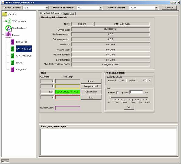
Colors green, yellow, red code
the node states: operational, preoperational, and stopped. The magenta color indicates
an unknown state, when no heartbeat is available.
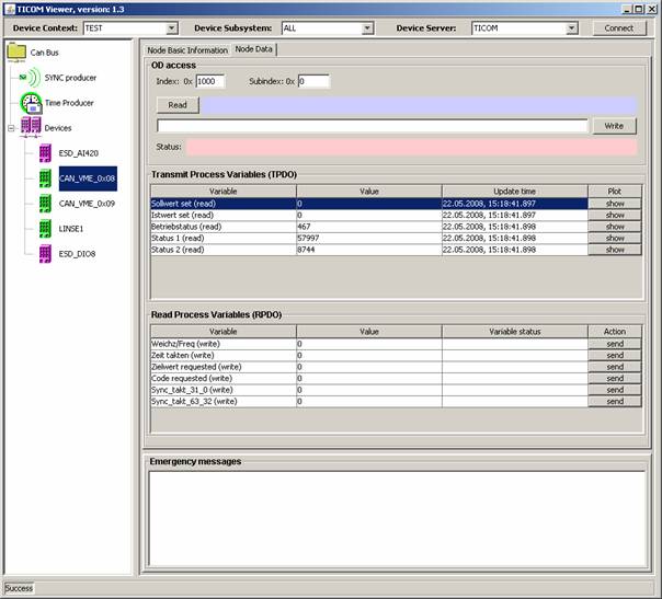
The “Node data” tab on the device
control panel provides access to the node’s Object dictionary.
Controls located in the upper part (OD access frame) of the
panel enable sending of SDOs to the selected CANopen node. Object dictionary
can store data of various types; the viewer performs the necessary conversions
automatically, for data being read or written. Two tables show the process
variables mapped currently to PDOs, values for process variables mapped to RPDO
can be typed to the appropriate table cell and sent.
Writing TICOM clients
As TICOM
is a TINE server all general guidelines for writing TINE clients remain valid: client
software addresses the device within the server and refer to its property,
reading or writing a property value.
There
are two categories of devices, available at TICOM: the devices of the first one
are always present, regardless of the number of CAN devices connected to the
bus, and represent the bus mastering functionality. The second group of devices
represents physical devices (CANopen nodes) connected to the bus, therefore the
size of the group can vary from 0 to 127. Names of CANopen devices are resolved
while parsing DCF files, during the TICOM startup procedure.
The tables
below present properties of CAN bus mastering devices.
|
Device
name |
|
|
|
COMAN |
Property |
ALLOP |
|
Description |
sends CAN message requesting all CANopen nodes to enter operational
state |
|
|
Access |
WR |
|
|
In-coming
data format |
null |
|
|
In-coming
data size |
0 |
|
|
In-coming
data meaning |
none |
|
|
Out-going
data format |
any |
|
|
Out-going
data size |
0 |
|
|
Out-going
data meaning |
none |
|
Device
name |
|
|
|
COMAN |
Property |
ALLPREP |
|
Description |
sends CAN message requesting all CANopen nodes to enter
preoperational state |
|
|
Access |
WR |
|
|
In-coming
data format |
null |
|
|
In-coming
data size |
0 |
|
|
In-coming
data meaning |
none |
|
|
Out-going
data format |
any |
|
|
Out-going
data size |
0 |
|
|
Out-going
data meaning |
none |
|
Device
name |
|
|
|
COMAN |
Property |
ALLRESET |
|
Description |
sends CAN message requesting reboot of all CANopen nodes |
|
|
Access |
WR |
|
|
In-coming
data format |
null |
|
|
In-coming
data size |
0 |
|
|
In-coming
data meaning |
none |
|
|
Out-going
data format |
any |
|
|
Out-going
data size |
0 |
|
|
Out-going
data meaning |
none |
|
Device
name |
|
|
|
COMAN |
Property |
ALLSTOP |
|
Description |
sends CAN message requesting all CANopen nodes to enter stopped state |
|
|
Access |
WR |
|
|
In-coming
data format |
null |
|
|
In-coming
data size |
0 |
|
|
In-coming
data meaning |
none |
|
|
Out-going
data format |
any |
|
|
Out-going
data size |
0 |
|
|
Out-going
data meaning |
none |
|
Device
name |
|
|
|
COMAN |
Property |
BUSINFO |
|
Description |
returns a structure contained general overview of CAN bus and TICOM |
|
|
Access |
RD |
|
|
In-coming
data format |
CF_STRUCT, tag: BUS_INFO typedef struct { long nNodes; char nodeName[127][33]; long nodeState[127]; long syncState; long timeProducerState; long busSpeed; char ticomVersion[64]; char ticomStartTime[64]; } BUS_INFO; |
|
|
In-coming
data size |
1 |
|
|
In-coming
data meaning |
number of devices, their names
and NMT states, state of SYNC
and time producer, bus speed, version of TICOM software, timestamp of TICOM
start |
|
|
Out-going
data format |
null |
|
|
Out-going
data size |
0 |
|
|
Out-going
data meaning |
none |
|
Device
name |
|
|
|
SYNC |
Property |
ON_OFF |
|
Description |
sets or gets the state of the SYNC messages generator |
|
|
Access |
RD/WR |
|
|
In-coming
data format |
CF_INT32 |
|
|
In-coming
data size |
1 |
|
|
In-coming
data meaning |
0 = OFF 1 = ON |
|
|
Out-going
data format |
CF_INT32 |
|
|
Out-going
data size |
1 |
|
|
Out-going
data meaning |
0 = OFF 1 = ON |
|
Device
name |
|
|
|
SYNC |
Property |
PERIOD |
|
Description |
sets or gets the period of SYNC
message generation |
|
|
Access |
RD/WR |
|
|
In-coming
data format |
CF_INT32 |
|
|
In-coming
data size |
1 |
|
|
In-coming
data meaning |
period in ms |
|
|
Out-going
data format |
CF_INT32 |
|
|
Out-going
data size |
1 |
|
|
Out-going
data meaning |
period in ms |
|
Device
name |
|
|
|
SYNC |
Property |
PERIODONOFF |
|
Description |
sets or gets in one call period and state of SYNC generator |
|
|
Access |
RD/WR |
|
|
In-coming
data format |
CF_INT32 |
|
|
In-coming
data size |
2 |
|
|
In-coming
data meaning |
[0] = OFF/ON [1] = period in ms |
|
|
Out-going
data format |
CF_INT32 |
|
|
Out-going
data size |
2 |
|
|
Out-going
data meaning |
[0] = OFF/ON [1] = period in ms |
|
Device
name |
|
|
|
TIMEPRODUCER |
Property |
ON_OFF |
|
Description |
sets or gets the state of the TIMESTAMP messages generator |
|
|
Access |
RD/WR |
|
|
In-coming
data format |
CF_INT32 |
|
|
In-coming
data size |
1 |
|
|
In-coming
data meaning |
0 = OFF 1 = ON |
|
|
Out-going
data format |
CF_INT32 |
|
|
Out-going
data size |
1 |
|
|
Out-going
data meaning |
0 = OFF 1 = ON |
|
Device
name |
|
|
|
TIMEPRODUCER |
Property |
PERIOD |
|
Description |
sets or gets the period of
TIMESTAMP message generation |
|
|
Access |
RD/WR |
|
|
In-coming
data format |
CF_INT32 |
|
|
In-coming
data size |
1 |
|
|
In-coming
data meaning |
period in ms |
|
|
Out-going
data format |
CF_INT32 |
|
|
Out-going
data size |
1 |
|
|
Out-going
data meaning |
period in ms |
|
Device
name |
|
|
|
TIMEPRODUCER |
Property |
PERIODONOFF |
|
Description |
sets or gets in one call period and state of TIMESTAMP generator |
|
|
Access |
RD/WR |
|
|
In-coming
data format |
CF_INT32 |
|
|
In-coming
data size |
2 |
|
|
In-coming
data meaning |
[0] = OFF/ON [1] = period in ms |
|
|
Out-going
data format |
CF_INT32 |
|
|
Out-going
data size |
2 |
|
|
Out-going
data meaning |
[0] = OFF/ON [1] = period in ms |
|
Device
name |
|
|
|
TIMEPRODUCER |
Property |
TIMESTAMP |
|
Description |
gets the current value of the TIMEPRODUCER |
|
|
Access |
RD |
|
|
In-coming
data format |
CF_INT32 |
|
|
In-coming
data size |
2 |
|
|
In-coming
data meaning |
[0] = time in ms [1] = date Meaning of time and date to according CANopen specification: time = milliseconds since |
|
|
Out-going
data format |
null |
|
|
Out-going
data size |
0 |
|
|
Out-going
data meaning |
none |
The devices,
which correspond to physical devices connected to the bus, offer a list of
properties, which again consists of ‘persistent properties’, common for all
CANopen nodes, and device-specific properties, which correspond to the
processes variables of the node.
The
tables bellow summarizes common CANopen node properties.
|
Device
name |
|
|
|
as in a DCF file |
Property |
EMCY |
|
Description |
emergency message emitted by the node |
|
|
Access |
RD |
|
|
In-coming
data format |
CF_STRUCT, tag: EMCY_INFO typedef
struct { long
timeStamp[2]; short emcyCode; char
errorRegister; char
manufactureSpecificCode[5]; char
isMessage; char
errorRegisterText[207]; char
emcyText[48]; }
EMCY_INFO; |
|
|
In-coming
data size |
1 |
|
|
In-coming
data meaning |
timestamp: UNIX time stamp with accuracy of milliseconds. Stored, when
emergency message was received. [0] – seconds, [1] – milliseconds. emcyCode: two bytes of the emergency message, according to CANopen
spec. errorRegister: contents of the
node’s error register (object dictionary index 0x1001) manufactureSpecificCode: 5 bytes of the code, freely defined by the
manufacture of the node hardware isMessage: 1 indicates validity of the structure contents, 0:
structure does not contain any data |
|
|
Out-going
data format |
null |
|
|
Out-going
data size |
0 |
|
|
Out-going
data meaning |
none |
|
Device
name |
|
|
|
as in a DCF file |
Property |
HbeatControl |
|
Description |
Heartbeat or node guard control |
|
|
Access |
RD/WR |
|
|
In-coming
data format |
CF_LONG |
|
|
In-coming
data size |
2 |
|
|
In-coming
data meaning |
[0]: state of heartbeat/node
guard monitoring. 0: inactive, 1: active [1]: period in ms defined for
the heartbeat messages |
|
|
Out-going
data format |
CF_LONG |
|
|
Out-going
data size |
2 |
|
|
Out-going
data meaning |
[0]: state of heartbeat/node
guard monitoring. 0: inactive, 1: active [1]: period in ms defined for
the heartbeat messages |
|
Device
name |
|
|
|
as in a DCF file |
Property |
IdInfo |
|
Description |
Device identifiaction data |
|
|
Access |
RD |
|
|
In-coming
data format |
CF_STRUCT, tag NODEIDINFO typedef struct { long nodeId; long deviceType; long vendorId; long productCode; long revisionNumber; long serialNumber; char
manufactureDeviceName[33]; char hardwareVersion[33]; char softwareVersion[33]; } CanNodeIdInfo; |
|
|
In-coming
data size |
1 |
|
|
In-coming
data meaning |
nodeId: the CAN node physical ID
bits ( “Physical address” set on DIP
switches, 1..127) deviceType: corresponds to the
Object Dictionary entry of 0x1000 vendorId: identifier assigned by the CiA to the manufacturer of the
node, OD entry (0x1018,1) productCode, revision number, serial number: arbitrary numbers
assigned by the manufacture of the node, correspond to OD entries (0x1018,2),
(0x1018,3), (0x1018,4) manufactureDeviceName, hardwareVersion, softwareVersion: arbitrary
strings, max 32 characters long, assigned by the manufacture of the node, OD
entries 0x1008,0x1009,0x100A |
|
|
Out-going
data format |
null |
|
|
Out-going
data size |
0 |
|
|
Out-going
data meaning |
none |
|
Device
name |
|
|
|
as in a DCF file |
Property |
NGuard_onOff |
|
Description |
gets/sets the state of the node guard message generator |
|
|
Access |
RD/WR |
|
|
In-coming
data format |
CF_LONG |
|
|
In-coming
data size |
1 |
|
|
In-coming
data meaning |
0: OFF 1: ON |
|
|
Out-going
data format |
CF_LONG |
|
|
Out-going
data size |
1 |
|
|
Out-going
data meaning |
0: OFF 1: ON |
|
Device
name |
|
|
|
as in a DCF file |
Property |
NGuard_period |
|
Description |
gets/sets the period of the node guard message generator |
|
|
Access |
RD/WR |
|
|
In-coming
data format |
CF_LONG |
|
|
In-coming
data size |
1 |
|
|
In-coming
data meaning |
period in ms |
|
|
Out-going
data format |
CF_LONG |
|
|
Out-going
data size |
1 |
|
|
Out-going
data meaning |
period in ms |
|
Device
name |
|
|
|
as in a DCF file |
Property |
NMTState |
|
Description |
gets/requests the NMT state of the node |
|
|
Access |
RD/WR |
|
|
In-coming
data format |
CF_LONG |
|
|
In-coming
data size |
1 |
|
|
In-coming
data meaning |
current NMT state of the node: 0x00: boot-up 0x04: stopped 0x05: operational 0x7F: preoperational if bit 0x8000 is set: timeout, no heartbeat message received from the
node |
|
|
Out-going
data format |
CF_LONG |
|
|
Out-going
data size |
1 |
|
|
Out-going
data meaning |
requested state of the node: 0x01: switch to operational
state 0x02: switch to stopped state 0x80:
switch to preoperational state 0x81:
reset node 0x82:
reset communication |
|
Device
name |
|
|
|
as in a DCF file |
Property |
ODentry |
|
Description |
reads/writes an Object Dictionary Entry (using a SDO) |
|
|
Access |
RD/WR |
|
|
In-coming
data format |
CF_STRUCT, tag: ODENTRYINFO typedef
struct { long index; long subindex; long dataCanType; long dataSize; char data[512]; }
ODentryDataInfo; |
|
|
In-coming
data size |
1 |
|
|
In-coming
data meaning |
Structured data contains index and subindex of accessed Object
Dictionary Entry, data type coded according to CANopen specification and data
size (both ignored, if requested entry can be located in the DCF file),
buffer for data. Please note the limit of 512 bytes, the property is not
suitable for a larger data block transfer (ex. firmware download) |
|
|
Out-going
data format |
CF_STRUCT, tag: ODENTRYINFO typedef
struct { long index; long subindex; long dataCanType; long dataSize; char data[512]; }
ODentryDataInfo; |
|
|
Out-going
data size |
1 |
|
|
Out-going
data meaning |
same as In-coming data meaning |
|
Device
name |
|
|
|
as in a DCF file |
Property |
RPDOvariables |
|
Description |
reads list of node’s process
variables |
|
|
Access |
RD |
|
|
In-coming
data format |
CF_STRUCT, tag: MAPPEDVAR typedef
struct { short index; short subindex; long long dataValue; // any numeric value fits here (64 bits of PDO) long long updateTime; short dataSize; short dataFormat; short npdos; // how many PDOs map this
variable short pdos[8]; // which PDOs map this variable char variableName[64]; }
MappedVariableValue; |
|
|
In-coming
data size |
64 |
|
|
In-coming
data meaning |
Array of structures, each of them contained mapping information of
process variable: index, subindex, data value, time of the last update (seconds,milliseconds)
data size, how many PDOs maps and PDO numbers, which map this variable,
variable name. Please note limits: variable name can not be longer than 64
characters, there can not be more than
8 PDOs, therefore not more than 64 process variables |
|
|
Out-going
data format |
null |
|
|
Out-going
data size |
0 |
|
|
Out-going
data meaning |
none |
|
|
|
|
|
|
Device
name |
|
|
|
as in a DCF file |
Property |
StateStat |
|
Description |
reads statistic of node’s NMT states |
|
|
Access |
RD |
|
|
In-coming
data format |
CF_LONG |
|
|
In-coming
data size |
10 |
|
|
In-coming
data meaning |
[0..3] counts of NMT messages,
received since TICOM start: boot, preoperational, operational, stopped [4..7]: Unix times stamps recorded, when node was booted, entered
preoperational , operational, stopped state [9]: Unix time stamp when the heart beat was considered as missing [10]: current NMT state of the node |
|
|
Out-going
data format |
null |
|
|
Out-going
data size |
0 |
|
|
Out-going
data meaning |
none |
|
|
|
|
|
|
Device
name |
|
|
|
as in a DCF file |
Property |
TPDOvariables |
|
Description |
reads list of node’s process
variables |
|
|
Access |
RD |
|
|
In-coming
data format |
CF_STRUCT, tag: MAPPEDVAR typedef
struct { short index; short subindex; long long dataValue; // any numeric value fits here (64 bits of PDO) long long updateTime; short dataSize; short dataFormat; short npdos; // how many PDOs map this
variable short pdos[8]; // which PDOs map this variable char variableName[64]; }
MappedVariableValue; |
|
|
In-coming
data size |
64 |
|
|
In-coming
data meaning |
Array of structures, each of them contained mapping information of
process variable: index, subindex, data value, time of the last update
(seconds,milliseconds) data size, how many PDOs maps and PDO numbers, which
map this variable, variable name. Please note limits: variable name can not
be longer than 64 characters, there
can not be more than 8 PDOs, therefore not more than 64 process variables |
|
|
Out-going
data format |
null |
|
|
Out-going
data size |
0 |
|
|
Out-going
data meaning |
none |
|
|
|
|
|
In case
of properties, which represent the process variables mapped to Transmit or
Receive PDOs, the format
corresponds
to the variable data type, as declared in the EDS or DCF file. Since they are
single variables,
the size
is always to be set to 1.
Some
Java examples:
- setting all devices to operational state
TLink l = new TLink(“/TEST/TICOM/COMAN”,”ALLOP”,null,null
,TAccess.CA_WRITE);
if( (error = l.execute(1000)) != 0 ) System.out.println("OD write error:
" + error + ", :"
+
l.getError(error) + ", " + l.getLinkStatus());
l.close();
- Writing the Object Dictionary entry (
0x1017,0 ) with value 500 to node named “ADC_10”
ODentryDataInfo input = new
ODentryDataInfo(); // constructor
of the
tagged structure for ODENTRYINFO
input.index[0] = 0x1017;
input.subindex[0] = 0;
input.data[0] = 500;
input.dataSize[0]=1;
input.dataCanType[0] = -1; // let server to figure out the
data type
String devname = new String( “/TEST/TICOM/ADC_10”);
TLink link = new
TLink(devname,"ODentry",null,new TDataType(input),TAccess.CA_WRITE);
if( (error = link.execute(1000)) !=0)
{
System.out.println("OD write
error: " + error + ", :" + link.getError(error) + ", "
+ link.getLinkStatus());
}
TicomView.TicomViewer.JLabel_odReadStatus.setText(link.getLastError());
link.close();
int[] adcValue = new
int[1];
int
error;
TLink link = new TLink( “/TEST/TICOM/ADC_10”,"INPUT_1",
new TDataType(adcValue),null,TAccess.CA_READ);
if( (error = link.execute(1000)) !=0) System.out.println("Error:
" + error + ", :" + link.getError(error));
else
System.out.println("ADC_10, INPUT_1 = “ +
adcValue );
link.close();
Bug reports, comments, wishes
concerning
TICOM, TicomViewer and this document are welcome and can be sent to piotr.bartkiewicz@desy.de