Introduction
TINE alarms are processed at two levels. The first level is located directly at the front end and is often refered to as the Local Alarm Server (LAS).
The LAS is a standard part of all TINE servers, independent of platform. Here, locally at the server, it is most easily determined whether an alarm is oscillating (coming and going), whether an alarm should append a heartbeat flag, whether an alarm has terminated, etc. The second level of processing occurs at a dedicated middle layer TINE server known as the Central Alarm Server (CAS). Here, alarms are collected, filtered, sorted, and made available for client-side review. The CAS also performs several additional tasks more appropriate to central level processing. It can determine whether 'server-down' alarms need to be issued in the case of a non-responsive server (something an individual server of course cannot do). It can also take actions following the receipt of particular alarms. For instance, it can issue post-mortem triggers, send e-mails, or write reports, supply annotations to archived data, etc. The TINE-Studio Alarm Viewer receives data primarily directly from the CAS.
It is also important to note the 'pulling' strategy used in accumulating alarm information. If a server detects an alarm, there might be a couple of ways to disseminate this information. A server could broadcast/multicast the alarm. This scenario was rejected out of hand. As it is desireable that no alarm information is lost, a server would have to broadcast its entire alarm table at all times in order that the CAS be guaranteed not to miss crucial information due to packet loss. A server could 'push' the alarm to the CAS. This scenario was deemed too restrictive. If the CAS is not running (for instance temporarily due to server restart), then once again an alarm might be lost, unless the server caches the alarm until it can successfully contact the CAS. Furthermore there could also be test- or secondary- servers which might want to process the alarms in addition to the CAS. The CAS identity is assumed to be a server called "CAS" running in the device server's context. As this identity is systematically known, a server will cache alarms until they have been read by the CAS. This essentially defaults to the same behavior as pushing an alarm to the CAS, but allows any number of interested clients to retrieve alarm information in the same manner.
The TINE LAS offers an alarm 'snapshot' consisting of five long integers, giving
- 1) the number of total alarms in the alarm table,
- 2) the timestamp of the most recent alarm in the list,
- 3) the highest severity in the alarm list,
- 4) the number of alarms at the most recent timestamp, and
- 5) the number of alarms at the highest severity.
The TINE CAS then monitors these snapshots from all relevant servers (configured by database) in the control system. As the monitor is a TINE DATACHANGE monitor, the CAS only receives the snapshot if one of these five integer values changes. The CAS can then retrieve alarm information from individual servers incrementally. Furthermore, alarms are not lost, as a server's alarm list is always accessible. If the CAS is restarted, it can quickly re-establish the current alarm situation.
TINE Alarm Structure
A TINE alarm as it exists at the front end consists of the following c-structure:
Some of the above fields warrant an explanation. The 'server' field refers to the device server or sub-system issuing the alarm. Typically this is nothing more than the device server name of the device server issuing the alarm. However it should be remembered that an alarm can be issued at a server on behalf of another (a middle layer, for instance). The 'device' field is the device name of the specific device responsible for the alarm. The 'alarmTag' field is a short alarm description, which should alert the operator to the primary nature of the alarm. The 'alarmCode' field defines the alarm as a number. Typically this will be a user-defined (i.e. server specific) code beginning at 512 which should be unique for each category of server. Alarm codes under 512 are interpreted as TINE systematic error/status codea (such as 'sedac_error' or 'gpib_error', etc.) if used. The 'timestamp' fields gives the UTC time of the alarm. The 'alarmMask' field is a user-defined (i.e. server specific) mask which can be used to further categorize an alarm. The 'alarmData' field is a place holder for up to 64 bytes of alarm-specific data, which can be used to provide any relevant information pertaining to the alarm in question (such as hardware address, high-resolution time information, threshold limits, a character string etc.).
The 'alarmDataFormat' gives the TINE format of the 'alarmData' field. The 'alarmDataArraySize' field tells in essence how much of the 64-bytes of alarm data are relevant. The 'severity' field gives the severity of the alarm (0 to 15). The 'descriptor' field gives the ORed descriptor flags pertaining to the alarm in question. Finally, the 'alarmSystem' gives a system-wide categorical description of the alarm system for which the alarm is relevant (e.g. 150 = Electron RF).
As noted above, TINE Alarms have a severity range of 0 to 15, where '0' is entirely informational, levels 1 through 7 are 'warning' level alarms. Severities above '7' are deemed critical, where the most extreme case '15' is usually reserved for immanent beam loss. Furthermore, TINE alarms can carry one of 7 different descriptor flags, defined by
almNEWALARM
almHEARTBEAT
almOSCILLATION
almDATACHANGE
almTRANSIENT
almDISABLED
almTERMINATE
almSUPPRESS
In general these descriptor flags can occur in combination. However in principle, certain combinations are mutually exclusive. For instance a 'NEWALARM' cannot carry the 'HEARTBEAT', 'OSCILLATION' or 'DATACHANGE' descriptor. The first appearance of an alarm for a particular device will carry the NEWALARM descriptor. If the alarm is unattended and remains in the LAS alarm list for at least 15 minutes, the 'HEARTBEAT' descriptor will be applied. If an alarm is cleared and ready to be terminated but abruptly returns, it will be assigned the 'OSCILLATION' descriptor.
If an alarm continues to be set by the front ends IO Loop, but with different data, the 'DATACHANGE' descriptor will be applied. Certain types of alarms do not have duration associated with them. Alarms such as hardware-error alarms, or threshold-exceeded alarms will remain in an alarm state until someone fixes the hardware or makes adjusts so that the threshold is no longer exceeded. However, beam-loss, quenches, RF-trips, and other types of transient alarms simply set an alarm following the occurrence of such a transient event, perhaps marking it with a high-resolution timestamp or issuing a post-mortem event, but do not remain in an alarm state for a duration. Such transient alarms will carry the 'TRANSIENT' descriptor. When an alarm is marked for termination it will carry the 'TERMINATE' descriptor, signaling the fact that it will be removed from the LAS alarm list in due course. Finally, a server can explicitly mark an alarm as a 'SUPPRESS' if desired.
It is interesting to note that a transient alarm will by definition carry the 'NEWALARM', 'TRANSIENT', and 'TERMINATE' descriptors when it is set.
Setting Alarms
How do alarms get entered into the LAS alarm table? Certain alarms are set only at the CAS. These might include 'server not responding' alarms (when the CAS has itself lost contact to the server), 'invalid epoch' alarms (when the timestamps of a monitored server claim a time more than 6 months in the past), 'cycle number stale' alarms (when the CAS itself is not regularly receiving new cycle/event numbers).
The local alarm system of each server might also automatically issue 'link error' alarms if the server depends on linked information from other control system servers and has stopped receiving such information. Likewise, an individual server might issue a 'disk space' alarm, if it has been configured to monitor available disk space on one or more mounted disks. Otherwise, establishing which alarm is to be set when is a task for each individual server.
Automatic Alarms
In the case of 'threshold-exceeded' alarms or 'pattern-not-matched' alarms, one can make use of an Alarm Watch database, which is read at initialization time and instructs the server engine to monitor the values of given properties and issue alarms if the read values fall above or below associated thresholds or do not match a given pattern. This method requires no extra coding on the part of the server developer. The Alarm Watch database can either be a text .csv startup file called almwatch.csv or under an ALARM tag within the PROPERTY section of 'fec.xml', or entries can be appended to the table via an API call appendAlarmWatchTable(). In some cases, server IO generates values of channels which should lie between certain boundaries for safe operation. Instead of using the max and min value range supplied during property registration, it was decided to allow separate registration of "watch" threshold values for relevant property values.
In the almwatch.csv file (or the appendAlarmWatchTable() API call), you can specify high and low thresholds as well as high and low "warning" thresholds. The local alarm server will then monitor those properties given and issue value_too_high, warn_too_high, value_too_low, warn_too_low alarms accordingly. You can likewise specify the severity such alarms should have. Alarms can also be automatically generated if a specific readback either does or does not match a given pattern.
For example consider the following almwatch.csv file:
The presence of this file at startup time (in the directory specified by the FEC_HOME parameter) will cause the local alarm server to check the property PRESSURE every 1000 msecs and compare all 600 float values read against the threshold values 0.5E-07 for issuing a warn_too_high alarm and against 1.0E-7 for issuing a value_too_high alarm. Values of 0 are given for the LOW and LOWWARN states, which in this case are not relevant. A single column 'SEVERITY' is given here which defaults to assigning the given severity (15) to value_too_high or value_too_low alarms and the severity minus two (13) to warn_too_high or warn_too_low alarms. Individual severities can also be specified by making use of the csv columns 'SEVERITY_HIGH', SEVERITY_LOW', 'SEVERITY_HIGHWARN', and SEVERITY_LOWWARN'.
The available csv columns within almwatch.csv or xml tag within the 'ALARM' tag are
- "LOCAL_NAME" gives the local equiment module name to which the call is to be made.
- "DEVICE_NAME" gives the device name to use in the monitoring call
- "PROPERTY" gives the property name to use in the monitoring call
- "SIZE" gives the data size to use in the monitoring call
- "FORMAT" gives the data format to use in the monitoring call
- "SEVERITY" gives a default severity to use in case of an alarm and in the absence of other information
- "SEVERITY_HIGH" gives the specific severity to use in case of a value_too_high alarm
- "SEVERITY_LOW" gives the specific severity to use in case of a value_too_low alarm
- "SEVERITY_HIGHWARN" gives the specific severity to use in case of a warn_too_high alarm
- "SEVERITY_LOWWARN" gives the specific severity to use in case of a warn_too_low alarm
- "ALARM_SYSTEM" gives a specific alarm system to associate with the alarm. If not given, then the registered alarm system at the CAS for the server will be used.
- "MASK" applies the given mask to the readback data before checking thresholds or patterns.
- "NORMAL" gives a pattern for a 'normal' readback value. If the readback value does not match the given pattern an 'invalid_data' alarm is issued. If the input value in this column is preceeded by a '!' (NOT) then only if the readback value matches the given value is an invalid_data alarm issued.
- "COUNT_THRESHOLD" gives the number of times a threshold exceeded or pattern mismatch must occur (consecutively) before an alarm is issued.
- "HIGH" gives the high treshold for a readback value before issuing an alarm.
- "LOW" gives the low treshold for a readback value before issuing an alarm.
- "HIGHWARN" gives the high warn treshold for a readback value before issuing an alarm.
- "LOWWARN" gives the low warn treshold for a readback value before issuing an alarm.
- "ALARM_CODE" gives an alternative alarm code to assign to a threshold or pattern mismatch alarm Otherwise 'value_too_high', 'value_too_low', etc.
- "ALARM_CODE_HIGH" gives an alternative alarm code to assign to a high threshold
- "ALARM_CODE_HIGHWARN" gives an alternative alarm code to assign to a warn high threshold
- "ALARM_CODE_LOW" gives an alternative alarm code to assign to a low threshold
- "ALARM_CODE_LOWWARN" gives an alternative alarm code to assign to a warn low threshold
- "ALARM_TAG_NORMAL" gives an alternative alarm tag to assign to an invalid data alarm
- "ALARM_TAG_HIGH" gives an alternative alarm tag to assign to a value too high alarm
- "ALARM_TAG_HIGHWARN" gives an alternative alarm tag to assign to a warn too high alarm
- "ALARM_TAG_LOW" gives an alternative alarm tag to assign to a value too low alarm
- "ALARM_TAG_LOWWARN" gives an alternative alarm tag to assign to a warn too low alarm
- "FILTER" gives a filter to be used in applying an alarm or not. If the filter criterion is correctly parsed and resolves to a valid control system address then the associated readback value is used to determine whether alarm conditions are valid or not. In the event of any error, conditions are assumed to always be valid. In other words, in order NOT to apply a watch table alarm a filter must be correctly parsed and correctly supply a readback value which does not fulfill the filter conditions. The filter string is parsed according to /<context>/<server>/<device>[<property>]<comparator><value> where <comparator> is one of "=", "!=", ">", or "<".
If a fec.xml configuration file is used, the relevant section will be embedded within the associated property and might look something like:
Special Cases
A device server can also optionally automatically detect 'low disk space' and issue an alarm. When the API call SetFreeBlocksAlarmThreshold() is used and points to a valid mounted disk and the remaining space on the disk falls below the given threshold, then a disk space alarm will automatically be generated. The available diskspace will be supplied in the alarm data.
CDI servers will likewise automatically set 'hardware error' alarms when an attempt to read or write to a hardware address results in an error. The hardware address of the deviced accessed will be supplied in the alarm data. If the number of hardware alarms surpasses the current 'alarm collapse window' the alarm server will (as always in such cases) issue a single alarm reflecting the best known state of affairs. In such a way 'alarm storms' (with largly uninteresting and irrelevant information) will not overwhelm the central alarm system and archive. The alarm collapse window can be set via the API call SetAlarmCollapseWindow().
Specific Alarms
Other varieties of alarms should be set inside a server's IO-loop. The suggested strategy is make use of two API calls, ClearDeviceAlarm() and SetDeviceAlarm(). At the beginning of the IO-loop, a ClearDeviceAlarm() should be called once for all devices (device number = -1). This will augment the alarms 'clear' counter. Then following hardware readout and other processing, alarms should be set as necessary using SetDeviceAlarm() for the device in question. A call to SetDeviceAlarm() will reset the 'clear' counter. If this procedure is followed, the LAS can determine if an alarm is oscillating or not, as the 'clear' counter must exceed a value of '8' in order for an alarm to be marked as terminated.
However if the 'clear' counter increases substantially on its way to eight and is suddenly reset, then the alarm is deemed to be oscillating.
This initial threshold value of '8' can itself be adjusted (incremented) by the local alarm system if it 'learns' of other oscillation criteria. Note that a readout error such as a hardware error might issue several alarms of different severity. The initial hardware error could for instance issue a 'hardware_error' alarm at a warning level, so that someone knows to fix the hardware. However the piece of hardware which is in need of repair might be critical for operations and hence a follow-up alarm 'critical-value-undefined' alarm might then be issued.
Transient alarms are likewise set with SetDeviceAlarm() where the Alarm Descriptor is explicitly set to almTRANSIENT. Such alarms of course do not need to be cleared, as they are marked immediately for termination.
Note in passing: The legacy API calls SetAlarm(), SetAlarmEx(), ClearAlarm() are still supported but will not be discussed here.
Alarm Definitions
The form of the SetDeviceAlarm() API call is fairly simple. In the TINE c-interface it looks like:
The first argument 'eqm' refers to the local equipment module name registered with the equipment module and is not present in an object oriented interface, where SetDeviceAlarm() appears as a method of a equipment module object.
An alarm is then specified in the call by four parameters, 'dev' giving the device name associated with the alarm, 'code' giving the alarm code associated with the alarm, 'data' giving any optional data associated with the alarm, and 'flags' giving any optional alarm descriptors associated with the alarm.
To the extent that 'data' and 'flags' are optional (i.e. data = NULL, and flags = 0 are allowed), it is primarily 'dev' the device name and 'code' the alarm code which determine the alarm.
How then does the LAS know what alarm tag to associate with the alarm code? Or if data are given, how does the LAS know how to interpret it?
It should be realized that the alarm code essentially defines the nature of the alarm, which is assumed to be 'static', i.e. alarm of type '578' always refers to the same kind of alarm.
Thus a startup database file alarms.csv is required to give the details behind any given alarm code. If the 'fec.xml' file is used, an 'ALARM_DEFINITION' tag within the 'EQM' section can supply the same information.
And, as usual, an API alternative exists via the AppendAlarmInfoTable() routine.
This startup database file will supply a human readable alarm tag to the alarm code (and give a longer description as well), supply the information necessary to interpret the alarm data, give the severity of the alarm, provide html links for further documentation, etc. If this startup file is missing, any alarm set will only be able to forward the alarm code along, with 0 severity and no description and no data.
An 'alarms.csv' (or 'ALARM_DEFINITION' xml tag) can contain the following csv columns (or xml tags):
- "ALARM_CODE" specifies the alarm code being defined. This is the 'cross-reference' between the SetAlarm() calls and the static information behind the alarm.
- "ALARM_TAG" gives a short description of the alarm (32 characters), essentially explaining in text what the alarm code is refering to.
- "ALARM_MASK" supplies a mask which may or may not be used by an application processing the alarms.
- "SEVERITY" provides a measure of severity for the alarm. This can be an integer value between 0 and 15, where the value '0' essentially implies a 'test' alarm and is not processed as a real alarm at all. The Central Alarm Server ignores alarms with severity 0. Traditionally alarm equal to or below severity '7' are treated as 'informational' or 'warnings', between the range '8' and '12', alarms are treated as 'problems' and above '12' are treated as 'fatal', where '15' designates that machine operation is impossible and '14' designates that machine operation will soon be impossible, etc. Where to use which severity is most often a matter of taste.
- "DATA_FORMAT" specifies the data format of any alarm data that should acccompany the alarm. Alarms can (but are not required to) contain up to 64 bytes of alarm data. This might provide the readback value which was over threshold, a hardware address, a text string, etc.
- "DATA_ARRAYSIZE" specifies the data size of any alarm data that should accompany the alarm.
- "ALARM_TEXT" gives a longer description of the alarm (64 characters). Note that the alarm 'tag' is always stored with the alarm itself, whereas the alarm text must be associated with a given alarm via consulting the alarm definition.
- "DEVICE_TEXT" gives a description of the device which has issued the alarm. As an alarm will 'belong' to a registered device, and the device name will always accompany the alarm, this text servers merely as a description of the kind of device the device name refers to (e.g. "getter pump", "beam position monitor", etc.).
- "DATA_TEXT" gives a description of the alarm data, if the alarm contains data. This should always contain useful text explaining what the data is. If a hardware address is provided, for instance, then examining the data might show 4 long integers. However without knowing (via the data text) what these integers refer to, the alarm data is almost useless.
- "URL" gives an optional url link where further information might be gathered in order to 'do something' about the alarm condition.
- "ALARM_SYSTEM" can be used to give a specific alarm system to associate with the alarm in question. Generally this will be either not provided or left as '0', which signals the Central Alarm Server to supply the alarm system. The alarm system is merely a 'number' kept at the Central Alarm Server to distinguish among the various possible subsystems (completely configurable). A server configuration attempting to provide this number must have knowlege of the configured alarm systems at the Central Alarm Server. On the other hand, this can be a useful parameter if a given server needs to set alarms for different subsystems (seldem the case, but it does occur).
As an example consider the following alarm definition file:
Thus by setting an alarm with a specific alarm code all other information concerning this alarm can be gleaned by consulting a lookup table based on the definition file.
The information in the above configuration file is used to fill in the alarm definition information maintained in the following structure:
When a fec.xml configuration file is in use, the embedded alarm definition subsection is associated with any and all registered devices managed by an equipment module. As an example, please have a look at the following:
Alarm Regions
The central alarm server can also provide alarm region information pertaining to the regional (within the facility) location of the device (or server) issuing an alarm. When a server initializes and discovers that it is being monitored by a CAS it will also acquire and update any regional information, if any. The CAS keeps regional information in two separate .csv configuration files: regions.csv and regionsdb.csv.
'regions.csv' maintains the specific enumeration cross-reference between region names and bit-wise enumerations (up to 16 bits). As an example, consider the regions.csv database:
which specifies a description with a region bit.
If there is a well-defined naming scheme, where a device name contains enough information to specify the regional location, then the regionsdb.csv need not be excessively long. In some cases all devices from a specific server clearly belong to a defined region within a facility, in which case patterns within a server name can suffice. If a pattern does not contain a wildcard character then the name must match exactly. Names not finding any sort of match will not have a known region.
As an example consider the regionsdb.csv file:
Alarm Viewer
The TINE Alarm Viewer can be started from any station. In the spirit of "one picture is worth a thousand words", we show below a (live) display of the alarm viewer for the FLASH accelerator. Note that the alarm viewer has several 'views', the default view being 'just' a subsystem panel showing each category and the number of active alarms in each cateagory. In our example we have exanded the view to also show the active alarms in a table (sorted descending by time).
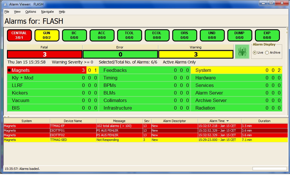
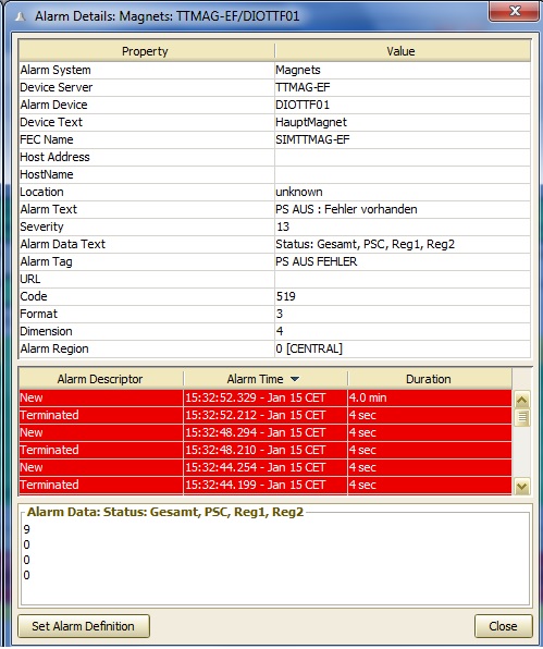
By clicking on any displayed alarm, one can obtain more detailed information. For instance, clicking on the Vertical Corrector Magnet (V.Korrekt.Mag.) 'Mag.Corr-LW/SVL127' we obtain a display containing more detailed information about this specific alarm, including its 'recent' history.
In live mode, the user can acknowledge alarms locally (within his instance of the alarm viewer) or globally, if he has permission. Globally acknowledging alarms is typically only allowed by the operators in the control room, and lets the alarm viewer always display the same information if several instances are running on different stations. As acknowledged alarms can still be viewed if desired, the casual user in his office can always see the current alarm state of the control system.
As can also be noted on the above display, the alarms are archived at the CAS and can always be recalled if desired. Otherwise, the alarm viewer generally displays alarms from the 'recent' past (last 2 hours) by default.
Central Alarm Server Configuration
The CAS does not collect alarms indiscriminately, but instead gathers only alarms from those servers deemed 'important'. Namely it reads its information from a configuration database.
The database follows the tradition of making use of flat .csv files and consists of a primary file called 'ServerList.csv' which lists the important servers and and other processing instructions and a cross-reference file called 'AlarmCodes.csv. There might also be secondary files which contain action responses when specific alarms arise.
As an administrator, one can avoid editing these files by hand by making use of the Alarm Database Manager, a snapshot of which is shown below:
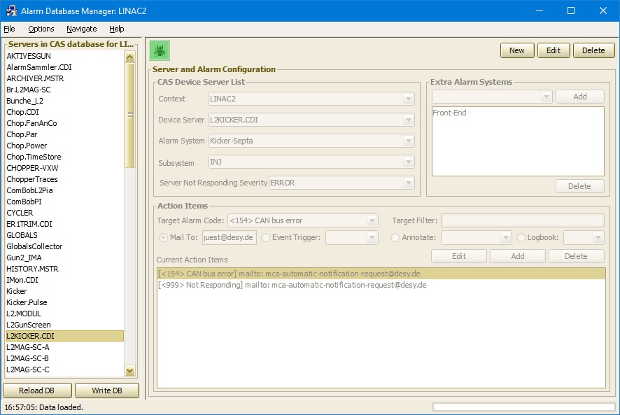
One can edit or add entries making use of the 'Update List' button, and when finished, clicking on 'Update DB' will send all information to the selected CAS and instruct it to re-read its database and restart.
Using the same managment tool, one can change the layout which appears in the alarm viewer GUI. By selection 'Options' -> 'Alarm Systems Manager' one call up another GUI component:
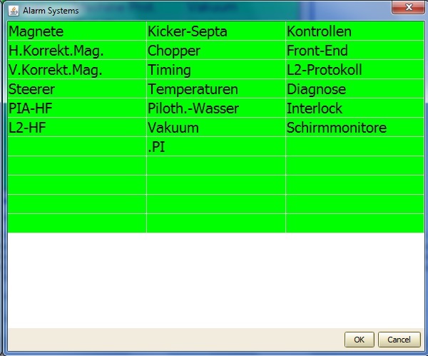
Here, one can add and remove alarm systems or rearrange the viewer grid by simple drag and drop.
The CAS is capable of starting up without a database, in which case it will make one based on querying the equipment name server (ENS) for 'IMPORTANT' Servers for its context. That is, if an administrator has marked (via the ENS administration tool) certain servers within a given context as having imporance = IMPORTANT or higher, then the CAS will automatically begin monitoring them, using the associated subsystem information as the alarm subsystems. This in itself will provide a general overview of the relevant alarm situation but may not be the best 'view' for operators. Fine tuning should be done either by hand or using the CAS database manager. In particular, if one needs to establish 'actions' associated with a specific alarm, this must be done with the database manager or by hand if you know what you're doing. 'Actions' might be sending a post-mortem event trigger, sending an email to a responsible person, annotating an archive keyword, or sending the alarm message to an electronic logbook.
For completeness, an example of the principal CAS database file, 'ServerList.csv' is shown below
One sees the following csv columns are in play:
- "CONTEXT" gives the context of the targeted device server.
- "SERVER" gives the context of the name of device server.
- "SEVERITYLEVEL" gives the minimal severity level for alarm managment (default 1).
- "ARCHIVELEVEL" gives the minimal severity level for alarm archiving (default 1).
- "RETENTION" gives the recent history retention (in seconds) to hold an alarm in local memory before committing to disk. (minimum = default = 60 minutes).
- "ALARMLEVEL" gives the severity to assign when issuing a 'server down' alarm. (default = minimum = 3 => 'INFO'; maximum = 15 => 'FATAL').
- "SUBSYSTEM" specifies the canonical subsystem associated with the device server. (optional).
- "ALARMSYSTEM" specifies the CAS defined alarm system associated with the device server. This typically provides a 'finer' split in sub system categories. For instance subsystem 'MAG' (magnets) can be split into (horizontal corrector magnets, vertcial corrector magnets, main magnets, etc.).
- "EXTENSION" specifes an archive extension for the device server. (default is the server name).
- "OFFLINE" Can flag a device server as 'off line' if non zero (optional). The value of 'offline' can provide specfic instructions if non-zero. In particular, if offline = '2' this specifies the instruction to 'INGORE_IF_NOT_RUNNING'. This specifically instructs the CAS to ignore any alarms from the designated server IF the state of the Context in which the CAS is running is marked as 'not running' by the state server. In the above example, if the state of 'LINAC2' is 'not_running' and alarms for a particular server have been flagged with offline = '2' then alarms will be ignored until the state of 'LINAC2' is no longer 'not_running'.
In addition, the CAS makes use of a CAS subsystem number and name cross-reference file called 'alarmCodes.csv', an example of which is shown below.
Here the following csv columns play a role:
- "NR" gives the CAS alarm subsystem number (used for each server in 'serverList.csv').
- "TAG" gives the CAS alarm subsystem as a human readable text string.
- "SUBSYSTEM" gives (repeats) the canonical assigned subsystem (optional).
- "ROW" gives the alarm viewer information as to which row to assign this CAS alarm system.
- "COLUMN" gives the alarm viewer information as to which column to assign this CAS alarm system.
The CAS will both read information files and maintain its own information files in a parallel directory/subdirectory called 'CACHE/AlarmInfo'. Each monitored server will maintain files here and specfically within subdirectories given by the 'EXTENSION' information found in the 'ServerList.csv file (shown above). The CAS itself will acquire the relevant alarm definition tables for the monitored servers and maintain a cache repository.
If a file named 'actions.csv' is found in the 'extension' subdirectory within this repository, the CAS will attempt to read it and if successful it will scan incoming alarms from the device server in question to see if a specific alarms requires an action. An example 'actions.csv' file is show below:
The relevant csv columns are given by:
- "ALARMCODE" specifies the alarm code which should trigger this action if it appears.
- "MAILTO" send an email to the email address give if the alarm occurs (other csv columns are irrelevant).
- "CONTEXT" send a trigger command and use this as the device context.
- "SERVER" send a trigger command and use this as the device server name.
- "DEVICE" send a trigger command and use this as the device name.
- "PROPERTY" send a trigger command and use this as the device property.
- "ACTIONFORMAT" gives the input data format if required (e.g. for a post-mortem trigger).
- "ACTIONSTRING" gives the input data, if required, as a string (to be parsed according to the ACTIONFORMAT).
- "ACTIONFILTER" provides a filter criterion which should be valid if the action is to be executed. If a filter is provide, it should be in the form: /em context/server/device[property]=value