(Click here for documentation in German).
Introduction
The access and control of hardware devices is typically achieved via fundamental 'Get' and 'Set' operations, where a 'Get' is used to acquire data or status information from the hardware bus and a 'Set' is used to change control modes or download data to the hardware. The details behind these simple operations are in general quite varied for disparate bus types. Some bus drivers offer single-channel read and write calls while others utilize duplex channels for read and write. Some bus drivers are single master, others are multi-master. The bus data format can also be different. For instance, RS232 deals with character string data, whereas SEDAC deals with short integers. The Can bus can deal with integers of various sizes. Hence the interfaces to these 'Get' and 'Set' operations are generally just as varied as the details behind them.
As all TINE developers are familiar with the TINE client API for accessing data from device servers, CDI strives to leverage this knowledge by offering the same API for accessing data from the hardware bus. In this case a device server running on a Front End Computer (FEC) is a client to its attached hardware. CDI itself offers a CDI-native API which is TINE-similar. However, by and large developers will want to make use of precisely the same TINE client API calls as used when accessing data from any other end-point in the control system.
Using the TINE client API to access the local hardware becomes a simple matter if the endpoint uses the device context "localhost", and the device server "cdi". Special parsing of the full device name also allows multiple endpoints with a single call. For instance, a call to "/localhost/cdi/device1" would access only the CDI device registered as "device1". On the other hand a call to "/localhost/cdi/device1 - device100" or "/localhost/cdi/device1,device3 - device10,device99" would identify the individual registered devices and access them as a group. The CDI property space includes the properties "RECV" for receiving (reading) data from the device, "SEND" for sending (writing) data to the device, "RECV.SEND.ATOM" and "SEND.RECV.ATOM" for issuing a pair-wise read-write or write-read operation which is guaranteed to be atomic, "RECV.CLBR" and "SEND.RECV.CLBR" for returning data which has been calibrated according to the registered calibration rules, and such properties as "ADDR" and "BUSNAME" which return information about the endpoint device. Other bus action properties are also available.
CDI Initialization
CDI operates on a plug-and-play basis, and adding a new bus interface plug to CDI only involves writing a new bus interface plug. The CDI shared library needs only to be compiled and installed once for the platform in question. On windows for instance this will be cdi32.dll (or cdi64.dll) and on Unix systems libcdi.so. Application platforms such as VB, or LabView will also access this same shared library. When the library loads, it will look for a CDI bus manifest file, which is a simple comma-separated-value file and can be as simple as a single column LIBRARY with a list of bus plug libraries, as shown below in figure 1.
CDI will then call cdiLoadLib() for each bus plug entry in the manifest list, for instance
cdiLoadLib("cdiCanEsd.dll");
on windows or
cdiLoadLib("libcdiCanEsd.so");
on Unix platforms, etc.
Additionally, the optional csv column BUS_ENV can be used to specify a process local environment variable for the given bus library. One can also optionally specify the bus name via the columns BUS and BUS_ID, although these are normally given via bus plug itself.
If the library loads successfully, it will (via its prologue code) register its name and all of its bus handlers with CDI, which itself has no a priori knowledge of any hardware bus interface. After the manifest has been read, CDI will look for a CDI device database and, if found, read it and register all devices and device information contained within. The registered information will include the bus name and address of the device and any accompanying bus parameters (such as bus speed) along with its assigned device name and number, as well as data access parameters and calibration rules. The supported calibration operations include addition (and subtraction), multiplication, and exponentiation along with bit shifting and modulo arithmetic on integer values. There is no limit to the number of calibration rules which can be applied, and they can be applied in any order, although care must be taken when mixing possible floating point rules such as multiplication or exponentiation with purely integer rules such as modulo arithmetic or bit shifting, so that the outcome of the calibration makes sense. We note here for completeness that CDI can operate without a database, but then all devices must be registered via API calls from with the server application. It should also be pointed out that writing a new bus plug for CDI is a relatively straightforward process. CDI itself will do nothing but load the bus plug library. It is the duty of the bus plug to register itself with CDI. There are a handful of CDI routines the bus plug should make use of in order to function properly. These are essentially all registration routines which provide CDI with the bus handlers for accessing its bus hardware (calls to open the bus, read and write to the bus, and close the bus). If a new hardware device has a driver API for the target platform, then the task of writing a bus plug is no more complicated than wrapping the appropriate API calls within the CDI bus plug handlers.
To this end, a "bus" plug does not itself have to interface directly to hardware, but could simply provide access to more complicated, generic hardware entities, such as "stepper motor" or "oscilloscope". These entities could themselves access the hardware directly (using CDI in a nested manner) and incorporate the "business logic" which handles the generic functionality that all "stepper motors" or all "oscilloscopes" etc. have.
In addition, complicated data calibration rules can be supplied in a like manner. Namely, a rules library can be included in the manifest as any other bus plug library.
CDI Environment
The following optional environment variables will be scanned upon initialization of the CDI subsystem.
CDI_HOME
Sets the location of the CDI manifest and CDI hardware address database. If this environment variable is not set, then the TINE environment variable FEC_HOME will be used to establish this location. If also not set, then the working directory is used.
CDI_LOG
Sets the location of the CDI log file. If this environment variable is not set, then the working directory is used.
CDI_GENERATEALARMS
Determines whether CDI will put bus errors into the TINE local alarm server (TRUE) or not (FALSE). The default is TRUE. See also cdiSetGenerateAlarms().
CDI_SERVERNAME
Will set the exported TINE CDI server name to the value given. The default is to make use of the registered FEC name and append ".CDI" (i.e. <FECNAME>.CDI). Note that Two CDI hardware servers running on the same machine will have a conflict if both see the same envirnoment variable. See also cdiSetExportName().
CDI_DEFAULT_POLLING_RATE
This variable, if set, will establish the default polling interval for internal queries to the CDI hardware server from the local history subsystem or the local alarm server subsystem. The default is 1000 milliseconds. See also SetDefaultQueryPollingInterval().
CDI_STANDALONE
If set to TRUE, this environment variable will disable the automatic TINE interface server to the CDI hardware and also disable the hardware access interace via the TINE client API, in which case, the native CDI access routines 'cdiExecLinkEx()' and 'cdiAttachLinkEx()' must be used.
CDI_FORCE_MCA_ACCESS
If set to TRUE, this environment variable will enable automatic enforced multi-channel array access of all 'extended' properties registered by the CDI server. This is by default not TRUE. However the default setting for this behavior might be changed in a future release.
CDI_EXCLUSIVE_READ
If set to TRUE, this environment variable will apply 'exclusive read' security to ALL bus access properties (such as 'READ', 'READ.CLBR', or any of the extended properties). The default setting is false, which means that any client can read (and cause read activity on the bus) any CDI bus property. If set to true, then the client's credentials (user name and network address) are checked against the same security information used for WRITE commands.
CDI_DEVICESERVERNAME
Will set the exported TINE companion device server name to the value given. The default is to make use of the registered FEC name and append ".CDI.SRV" (i.e. <FECNAME>.CDI.SRV).
Note that two CDI hardware servers running on the same machine will have a conflict if both see the same envirnoment variable. See also cdiSetDeviceServerExportName().
CDI Configuration Details
CDI Manifest
As noted above, the CDI manifest is a required file (found in the CDI_HOME or FEC_HOME location) and determines which hardware busses are to be supported on the local machine. This is a simple comma-separated-value (csv) file, which need contain only a single column 'LIBRARY'. For example,
The above example instructs CDI to load the libraries for the CanEsd, cdiSedUsb, and TwinCATads bus plugs. (If a single station actually supported all of these hardware types that would indeed be unusual!). On a Windows machine, the DLLs CanEsd.dll, cdiSedUsb.dll, and TwinCATads.dll will be searched for on the path and loaded. On a UNIX machine, the shared libraries CanEsd.so, cdiSedUsb.so, and TwinCATads.so will likewise be loaded.
The CDI manifest can optionally contain the column 'BUS_ENV' to specify general environment settings for a specific bus plug and/or the column 'SIMULATION' which, if it contains a non-zero value, instructs CDI to simulate the hardware access (useful for testing on stations where the hardware is not attached).
CDI Address Database
When the individual bus plugs load, they will register all hardware access and dispatch routines with CDI following which, CDI will then look for and read a CDI address database file called 'cdiaddr.csv', also located in the CDI_HOME (or FEC_HOME) directory. A simple example is shown below:
In the above example, the csv columns 'NAME', 'BUS', 'LINE', 'ADDRESS_BASE' and 'FORMAT' are all required. In fact, CDI will refuse to load the database if one of these columns is missing. The missing column(s) will be indicated in the cdi.log file (also written in the CDI_HOME directory). Note that by and large a particular station will most likely only have attached hardware on a single type of hardware bus and not the ad hoc mixture of CAN, SEDAC, and TwinCat shown in this example.
- 'NAME' identifies the CDI device associated with the address information give. An internally assigned device number can be obtained from CDI following the database load (or it can be assigned explicitly by including a 'NUMBER' column in the address database).
- 'BUS' identifies the CDI Bus to be used to access the CDI device. This will be the BUS name supplied to CDI via the Bug plug library. This is NOT the name of the bus plug library. For example, if the cdiSedUsb library identifies the bus with the tag "SEDUSB", the the 'BUS' should also be "SEDUSB". Note that additional bus parameters can also be supplied if necessary (using a ':' delimiter). For instance, if the CAN bus speed needs to be specified on a device basis, etc.
- 'LINE' identifies the CDI line on which the bus operates. This number is passed on to the bus plug and constitutes part of the CDI device's address. For example CAN line 1 and CAN line 2 might be two physical hardware field bus lines attached to the station.
- 'ADDRESS_BASE', 'ADDRESS_PARAMETERS', and 'ADDRESS_MAP' all server to completely specify the CDI device's hardware address. 'ADDRESS_BASE' is absolutely necessary (even if it contains a '0') and can contain up to 16 integer values (separated with a '.' delimeter). These will be passes on the CDI bus plug.
'ADDRESS_PARAMETERS' can also contain up to 16 integer values separated by a ':' delimiter) to further specify address information (additional sub registers, ip address information, etc.) which might be needed by the bus plug. 'ADDRESS_MAP' provides character string information needed to specify the CDI device's address (as might be needed by bus plugs such as TwinCAT, which use memory mapped PLC locations). - 'FORMAT' gives the BUS format (for read/write io) for the CDI device specified. Frequently this is the same format for a given bus (e.g. SEDAC is always 'short'). However some busses (CAN) can use integers of any length on the same line, depending on the io request.
- 'PATTERN' is an optional column, but present in the above example to indicate which io readback 'patterns' are to be matched in order to validate the data. In the above example, the CAN PDO is looking for specific value patterns on the address information given in order to identify the incoming data as belonging to the CDI device specified. The TWinCAT address likewise makes use of the same technique.
Additional optional columns include:
- 'MASK' which if present will mask all readback data with the value given. Note: then value '0' will effectively null out the readback data and is not equivalent to an empty entry!
- 'ACCESS' can specify one of "READ", "WRITE", "READWRITE", "WRITEREAD", "WRITEREADWRITE", "READREAD", or "WRITEREADREAD", or a combination of these options separated by the stander OR character '|' (i.e. "READ|WRITE". The abbreviations "RD" for "READ" and "WR" for "WRITE" are also allowed. If not given, then all access modes for the CDI device given will be accepted by CDI. "READ" and "WRITE" access do not need any further clarification. However a word about the other modes is in order. In the other cases an atomic operation is performed on the bus consisting, for instance in the case of "WRITEREAD" of an write operation using the given 'WRITE' address parameters and a read operation using the given 'READ' address parameters. Note that some hardware io operations will require such atomic access of the registers in order to obtain the appropriate readback value or to set up the appropriate sendto value. In such atomic calls, the address parameters and access will be passed to the bus plug, which is required to know what to do with the information. Typically a "WRITEREAD" would have at least two address parameters, one for the write address register and one for the read address register (and possibly two address base parameters as well) which identify the atomic bus request. In addition, the options 'LSN' or 'HIST' can be applied to the access string, likewise separated by the OR character. If 'HIST' is applied then a local history of the given CDI device will automatically be taken (using the standard 1-month, 10-minute history settings). If 'LSN' is applied then a listener will automatically be applied to the given CDI device. Note the 'HIST' will effectively start a listener as well. In either case the corresponding 'extended property' of the device will be used for access. Needless to say, the 'READ' access will need to be applied as well in order for this to function property (e.g. access = "READ|LSN"). The update interval used in these cases will be that supplied in the address database or the default interval, if none is present in the databse.
- 'INPUT' can be used to specify bus input data to be used in calls which do not directly supply input data. The input data will be parsed according to the 'FORMAT' specified and used for instance in "WRITEREAD" calls which do not supply bus input data and in "WRITE" calls where a '=' SEND calibration rule is in force.
- 'LIMIT' can be used to specify a limit to the maximum size a READ or WRITE operation is allowed to process.
- 'RULE_RECV' can be used to define calibration rules to apply to readback data following 'READ' operations. The available calibration rules will be described below, but we note here that CDI calibration rules take only a single data value as input and deliver a single data value as output. It will not be able to process multiple CDI readback data to form a result. The resulting data can be obtained by using the bus property of type 'RECV.CLBR' or 'SEND.RECV.CLBR', etc.
- 'RULE_SEND' can be used to specify reverse calibration rules to apply to bus input data prior to sending out on the bus. The available rules will be described below.
- 'DESCRIPTION' can be used to supply descriptive text relating to the device given. Additional CDI device information can be supplied here by including such things as range, units and precision by including this within brackets '[' and ']' within the description text. If included, this should be of the form "[range=0:100 units=V precision = 4.2]". This additional information will be parsed away from the CDI description proper and be available via selecting the CDI properties "RANGE", "UNITS", and "PRECISION" for the desired CDI device.
- 'INTERVAL' can be used to supply a 'default' polling interval for the device in question. The value of the default polling interval ('1000 msec' if not otherwise specified) will be applied to all cdi 'listeners' which are started on behalf of any monitored requests (unless the initial monitor request specifies an interval smaller than the default, in which case the smaller value will be used).
Note that no matter how many clients end up monitoring a device, the initial monitor call establishes the 'listener' interval.
CDI Scheduling
A CDI server is also capable of scheduling output for 'extended' properties (see below) to any and all listening clients. If a monitor contract for an extended property is active, then following each hardware access the output can be scanned and compared against the previous readback and then scheduled or not based on the configured tolerance criteria. As a call to an 'extended property' does NOT involve a direct call to a CDI device with a 'bus' property, the polling interval is established via the initial monitoring call, which could be a local history call, in which case the CDI_DEFAULT_POLLING_RATE environment variable plays a role. In any event, this could be a much smaller interval than a particular client has specified, but the client could then be assured of receiving relevant changes quasi-immediately if the 'extended' property is scheduled.
To define which extended property are scheduled, an additional csv configuration file called 'cdiched.csv' needs to be supplied. This should contain two columns specifying the PROPERTY to be scheduled and the TOLERANCE which should be applied in determining when to schedule. For example:
The extended property 'P1' is scheduled on any readback as the tolerance is '0'. The extended property 'P2' is scheduled only when the readback value changes by 10% compared to the previous readback.
- Note
- There is no additional buffer of the 'last scheduled value' to use in a tolerance comparison. This can lead to a 'creep' in the scheduling criteria, if the 'last readback value' is always just within tolerance but steadily grows or shrinks.
CDI Companion Device Server
Another and in most cases better way of scheduling data from a CDI Server is to set up a 'companion' device server. This is another (in-process) exported device server which essentially turns an otherwise passive CDI server into an actively updating device server capable of scheduling data to clients. If 'exclusive read' (see above) is in play, then clients in general will not be able to access data directly from the CDI server itself. The companion * device server, on the other hand, is in-process and setup to readout all relevant data at a configurable readback update rate, calibrate them, and make them available to outside client. This is in effect a way of reflecting the hardware memory (which may be at a remote location on the ethernet) to a local server.
The data readback can also check assigned tolerances and schedule data to clients as necessary.
The companion server deals with 'calibrated' data and as such can re-export all of the 'extended properties' of the standard CDI server as well as its 'READ.CLBR' property. However, which of these is re-exported is a question of setting up the proper database.
This is an additional .csv File called 'cdiserv.csv', which if present will signal the CDI server to read its contents and export a companion server, which by default will have the same name as the CDI server with the final decoration ".SRV" appended. This name can be assigned either by making use of the environment variable (see above) CDI_DEVICESERVERNAME or the api call cdiSetDeviceServerExportName().
In the above file, the column 'PROPERTY' is required and must be a valid extended property. Any or all of the known extended properties can be included (one per line), even if it refers to a single scalar readout.
Optional columns include
- 'DEVICE' should specify the associated extended propety device used to access the information from the CDI server. If omitted, a '#0' will be used in its stead. For those scalar extended properties where the associated device has the same name as the property, then this become irrelevant.
- 'FORMAT' gives the desired data format to use to access the extended property from the CDI server. If omitted, 'CF_FLOAT' is used. This is the default registered data type for any extended property as the calibration rules will be applied, which often render the data readback into a floating point number. If it is known that the values should be read back as for example a 'short integer' then one should fix that here.
- 'SCHEDULE_TOLERANCE' gives the tolerance string to use for scheduling data to clients. If omitted, then the readback data will not be scheduled. Otherwise the data will be compared against the previous readback in making the scheduling decision (same logic as noted above).
- 'SIZE' gives the desired datasize of the extended property access. If omitted, then the full registered property size will be used.
- 'INTERVAL' gives the desired readback update interval in milliseconds. If omitted, a value of 1000 is used (corresponding to readback at 1 Hz).
- 'KEEP_HISTORY' is a boolean indicating whether the companion device server should maintain a local history of the extended property. If 'TRUE' this will apply the 'default' local history criteria of a short-term depth of 600 entries in a ring buffer, 1 month storage on the local disk, and readbacks at 1 Hz, storing to disk when a tolerance of 10% has been exceeded or a heartbeat of 15 minutes has passed. If more refined local history criteria are needed, then the use of a history.csv should be employed.
Calibration Rules
As noted in the above section on configuration details, you can supply calibration rules to both input data (data to send to the bus) and output data (data to receive on the bus). Data calibration will involve a train of operations on a single input and provide a single output. Calibration rules are supplied in the form '<operator><operand>:<operator><operand>:<operator><operand>' and applied in a progressive manner. For example
*10.0
will take the input and multiply by 10.0,
*10.0:+2.345
will take the input and multiply by 10.0, and then take the result and add 2.345. Generally, calibration will result in a (double precision) floating point number as a result, regardless of the original bus format (frequently a short integer). Some calibation rules of course involve integer arithmetic. However as the rules are applied sequentially, it is important to remember that the first non-integer rule applied will result in a floating point result.
The available rule set consists of
- '+' add the operand.
- '-' subtract the operand.
- '*' multiply the operand.
- '/' divide by the operand.
- '^' raise to the power of the operand. e.g. ^5 will take the current value and raise it to the 5th power.
- 'L' take the logorithm (base 10). n.b. there is no operand here.
- '' take the modulo with respect to the operand.
- '>' shift right by the number of bits given by the operand.
- '<' shift left by the number of bits given by the operand.
- 'U' treat the current values as unsigned. n.b. there is no operand here.
- 'S' treat the current values as signed. n.b. there is no operand here.
- 'M' Apply the text operands as a 'true' message or 'false' message depending on the current value. e.g. M<ON><OFF> will return "ON" if the current value evaluates to 'TRUE' and "OFF" if it evaluates to 'FALSE'. For this rule to be useful, a 'MASK' is sometime applied to the readback data. The result must of course be read out as a text-based data type. n.b. This rule will break the rule chain at the point of application.
- 'E' raises the operand to the power of the current value (opposite of '^'). e.g. E5 will take '5' and raise it to the power of the current value.
- '|' applies the rules function given by the text operand to the current value. If the function is not found in the rules registry, then no operation occurs. e.g. |bits2val will look for a registered function 'bits2val which takes a single double value as input and returns a double value. If found this function will be called with the current values as input.
- 'F' alternative to '|'.
- 'O' applies an OR with the operand.
- 'X' applies an XOR with the operand.
- '~' applies a NOT with the operand.
- '&' applies an AND with the operand.
- '=' fixes the current value to the operand (available only for RULES_SEND). e.g. =3 will send a '3' to the bus on any write operation, regardless of whether input data are provided or not.
- Note
- Rules are truncated to the first character by the rules parser. Thus the rules description in the database file can be a bit more descriptive if desired, i.e. 'MSG' instead of 'M', 'XOR' instead of 'X', or 'FCN' instead of 'F'.
When a rules function is used (because the calibration is otherwise too complex to realize with a simple rules chain), then the calibration function must be registered with CDI. In this case, the CDI manifest will contain an additional library to load at initialization. But instead of registering a bus plug, it will register one or more calibration functions. This (these) will be a function of the form
double myFunction(double value);
and should register this function by calling cdi_RegisterCalibrationFunction() in the libraries prologue routine.
Note the difference between RULES_RECV and RULES_SEND. With RULES_RECV, the raw readback data from the bus is always available via the bus action properties "RECV", "SEND.RECV.ATOM", etc. whereas the calibated values is available via "RECV.CLBR", "SEND.RECV.CLBR", etc. In the former case, the bus plug format can be used to obtain the raw bus data. Any other data type can also be used, but will require format conversion. In the latter case, the application of most rules will involve some form of format conversion and will in some cases require the caller to use an appropriate data type in order to get meaningful results (for example where a Message rule is applied). If the CDI hardware server is called using CDI device properties as opposed to bus action properties such as 'RECV', then the CDI server makes the mapping decision to apply calibration rules prior to returning the results.
With RULES_SEND, the input data must be converted back to the bus format and to raw hardware data prior to transmission to the hardware. One should be wary of roundoff errors that might occur during some calibration steps.
CDI Templates
In the examples above we have been dealing with a rather simple database with a few devices. Most cases are of course much more complex. In particular, hardware modules will typically have repeating patterns which might require tedious copy-and-paste activity if not for CDI templates.
Suppose for example, we have hardware devices "HDW1", "HDW2", "HDW3", and "HDW4" and they all refer to a certain kind of hardware device module called (for want of a better example) "SEKI". And suppose Each SEKI module has 4 address offsets which refer to different things about a SEKI module. So rather than making 4 X 4 entries in our database (note: this could be a lot worse!) we can simplify life be first registering the SEKI module as a CDI TEMPLATE and marking each of our hardware devices a SEKI module.
In the above we have registered a CDI template called "SEKI" by declaring the template entries to 'belong' to the bus type "TEMPLATE" (which is a special reservered keyword). Furthermore, we have given all CDI 'device names' for the template entries in the form '<template name>:<field name>', e.g. 'SEKI:sts'. CDI then knows to maintain a template entry for 'SEKI' in its template registry and add the field 'sts' with the address parameters given. The 'ADDRESS_BASE' is ignored (and should contain a '0'). All template fields for the template type are added to the CDI address database in this manner.
A named entry will then specify the proper bus type (in our example 'SEDPC'), give a valid ADDRESS_BASE and then specify the '<template name>' in the ADDRESS_PARAMETERS database column. In this way the named devices for a given template branch into CDI devices for all registered fields. The registered CDI device names will be a composite of the entered CDI device name joined (inserting a '.' delimiter) with the template field names. In the example above, CDI will register 'HDW1.sts', 'HDW1.soll', 'HDW1.pwr', 'HDW1.hv', and so on for the other database entries.
- Note
- Template field names can contain up to 16 characters. The given CDI device name can contain up to 32 characters. However, if the CDI device module name itself is longer than 16 characters and then appends template fields to form the final registered CDI device names, the resulting device names will be truncated at 32 characters. One must bear this in mind when assigning device module names and template field names.
CDI Bitfields
In is also possible to assign names to individual bits or bit fields in CDI. This is done by registering a TINE BITFIELD and assigning, in this case, the FORMAT field to the bit field type and name in a similar manner as is done in assigning a template. Indeed, a CDI template can itself contain bitfields as shown in the example below.
In this case, a bitfield 'BF1' is registered by using the reserved keyword 'BITFIELD' as the ADDRESS_BASE and and suppling the bitfield field names as one would a template field ('<bitfield name>:<field name>'). Here the 'MASK' column is essential, as it will define which bit or bits make up the TINE bitfield. The bitfield is then entered in the bitfield registry with the bitfield name given (here 'BF1').
In the above example, a template 'TrgtRvlvr' is then registered, which uses this bitfield in its 'Status' field. The bus format should include one of BITFIELD8, BITFIELD16, BITFIELD32, etc, followed by the bitfield name, in the form 'BITFIELD16:<bitfield name>'. The registered CDI devices will not specifically include the bitfield fields, as the integer carrier is always transfered in its entirety. However, the CDI hardware interface will register and respond to full address queries such as 'S21Trgt.Status.T1IstInPos'. This means that (in such a nested case as this) the 32-character name limitation applies only to the CDI module name and template field, but not to the bitfield fields. The registered TINE device can hold up to 64 characters.
- Note
- Bitfields in this manner can provide easy READ access to individual bits, but NOT WRITE access! CDI cannot know a prior what descisions to make regarding writing a single bit to the hardware, as hardware modules typically accept an entire WORD or DOUBLE WORD (i.e. ALL bits). One can effectively generate the same view of a READ/WRITE bit by registering an additional CDI device as WRITE only and provide the appropriate MASK and entire device name (down to the bitfield level) thar otherwise appears from the bitfield registration.
CDI Field Bus Names
CDI can also provide a useful field bus name to a CDI bus line. This itself does not enter into any CDI bus logic but provides a good diagnostic for easily determining what exactly is connected to the hardware bus line. If no other information is provided, CDI will return a marginally useful field bus name such as "CAN-Line1" if a device uses the can bus and is on CDI line 1. If registered, CDI could instead provide a name such as "BPMs-Hall-West", etc.
One can supply this information by adding a line to the CDI database using the reserved keyword "FIELDBUS" as the 'BUS' name. In this case, the relevant CDI address database columns are 'LINE', 'NAME', and 'BUS'. The 'NAME' should contain the field bus type (e.g. 'CAN') followed by the field bus name in the form '<bus name>:<field bus name>'. In the above example, a field bus name "BeamTargets" was assigned to the 'SEDPC' line 1 bus.
- Note
- Regarding the addition of CDI Templates, Bitfields, and Field bus names within the CDI database, it is worth noting that the CDI database is initially scanned for field bus names. Then it is scanned for bitfields. Then it is scanned for templates. Finally it is scanned for module and device addresses. So, although it might make intuitive sense to actually include Field bus names, Bitfields, Templates, and devices in the CDI address database in this order, it is not necessary.
CDI Character Set
As perhaps gleaned from the above discussion, the CDI address database makes use of certain special characters while reading in informatino from the database. Namely, the characters '.' and ':' are often used as delimiters in parsing address information. Similary, '<' and '>' are used in establishing template names and message sets, etc. CDI device names should perforce avoid these characters. In addition, the use of blanks and slashes '/' in device names (athough allowed by TINE) is not a good idea in general. Finally, as 'cdiaddr.csv' is a comma separated value file, commas should certainly be avoided in names. If the device description requires a comma, then the device string should be enclosed in quotes '"'. The CDI database manager will check for these sorts of things, but if you make the cdi address database by hand using Excel or some other spreadsheet, then you should beware of these issues.
CDI device names can contain up to 32 characters total. In is usually prudent to try to restrict names to 16 characters or less, particularly where templates or bitfields are involved. In such cases the registered CDI device names will be the template instance name plus the template field names which could result in an unexpected truncation.
CDI Hardware Server
As mentioned above, the CDI subsystem will provide a so-called hardware server servicing the CDI devices found in the local hardware database. This hardware server exists both as a logical 'in-process' server accessible via the TINE address '/localhost/cdi' and as an exported device server with default context as the server's registered context and default server name given by the registered FEC name appended with ".CDI". Thus, clients to CDI can either be 'in-process', whereby all CDI devices are address via the 'localhost' context or 'out-of-process', whereby the CDI devices are addressed via the exorted context and device server. However, note, if it is discovered that the addressed context and device server end up pointing to the same process making the call, then the CDI access collapses to in-process direct access.
It should be clear that 'in-process' communication will deliver the best performance, makes the most efficent use of the CDI threading logic and provides the most direct control over how the hardware is accessed. A device server accessing its hardware via remote access calls to the exported CDI hardware server will involve many more layers, latency, and potential timeouts between the hardware readout and the readback values reaching the process.
However, using the CDI hardware server remotely provides a good way to decouple the physical hardware, which might be connected to a remote station, and the device server logic, which might be running on a desktop station in debug mode. Howeve, as noted above, if the device server does make use of the exported device server names (e.g. /LINAC2/RF.SLED.CDI/Sled01.Delay instead of /localhost/cdi/Sled01.Delay) and is run together with CDI enabled within the same process on the same machine, then the communication will also collapse to 'in-process'.
The CDI hardware server will make the following 'bus action' properties available:
- SEND Issues a CDI Write Telegram(s) to the device(s) specified
- RECV Issues a CDI Read Telegram(s) to the device(s) specified
- SEND.CLBR Issues a CDI Write Telegram(s) to the device(s) specified and applies the known (reverse) calibration rules to the input data prior to sending.
- RECV.CLBR Issues a CDI Read Telegram(s) to the device(s) specified and applies the known calibration rules to the output data prior to returning to the caller.
- SEND.RECV.ATOM Issues an atomic CDI Write+Read Telegram Pair to the device(s) specified
- RECV.SEND.ATOM Issues an atomic CDI Read+Write Telegram Pair to the device(s) specified
- SEND.RECV.CLBR Issues an atomic CDI Write+Read Telegram Pair with calibration to the device(s) specified and applies the known calibration rules to the output data prior to returning to the caller.
- SEND.SEND.ATOM Issues an atomic CDI Write+Write Telegram to the device(s) specified
- SEND.RECV.SEND.ATOM Issues an atomic CDI Write+READ+Write Telegram to the device(s) specified
- RECV.RECV.ATOM Issues an atomic CDI READ+READ Telegram to the device(s) specified
- SEND.RECV.RECV.ATOM Issues an atomic CDI Write+READ+READ Telegram to the device(s) specified
- RECV.SEND.CLBR Issues an atomic CDI Read+Write Telegram Pair to the device(s) specified and applies the known (reverse) calibration rules to the input data prior to sending.
- SEND.SEND.CLBR Issues an atomic CDI Write+Write Telegram to the device(s) specified and applies the known (reverse) calibration rules to the input data prior to sending.
- SEND.RECV.SEND.CLBR Issues an atomic CDI Write+READ+Write Telegram to the device(s) specified and applies the known (reverse) calibration rules to the input data prior to sending.
- RECV.RECV.CLBR Issues an atomic CDI READ+READ Telegram to the device(s) specified and applies the known calibration rules to the output data prior to returning to the caller.
- SEND.RECV.RECV.CLBR Issues an atomic CDI Write+READ+READ Telegram to the device(s) specified and applies the known calibration rules to the output data prior to returning to the caller.
All of the properties above involve directly accessing the attached hardware. A number of informational properties are also provided. These include the following CDI device information properties:
- BUSTYPE Gives the bus type in use by selected device
- BUSADDR Gives the hardware address in use by selected device
- BUSNAME Gives the fieldbus in use by selected device
- DESCRIPTION Gives the description of the selected device
- NUMBER Gives the CDI device number (plus line and index) assigned to selected device
- RANGE Gives the value range (calibrated) for selected device
- UNITS Gives the assigned units (calibrated) for selected device
- PRECISION Gives the assigned format precision (calibrated) for selected device
General CDI diagnostic properties include:
- LINESTATUS Provides the CDI line status for the CDI line given (Number active requests)
- BUSERRORS Provides the number of bus errors since server start
- BUSSCAN Issues a bus scan according to input text given. A bus scan is usually very bus specific. The input text "help" should be consulted at to the available scanning possibilities.
Finally there are additional properties which provide configuration information. These include:
- TEMPLATE Provides template information for the template specified
- NINSTANCES Gives the number of objects using template specified
- INSTANCES Gives the object names using template specified
- BUSTYPES Gives the Supported Bus types
- BUSDEVICES Gives the registered CDI devices for give bus line
- BUSNAMES Gives the supported Bus names
Extended Properties
If one browses a CDI hardware server with a control system browser (such as the TINE Instant Client) one will also see additional properties, namely the template fields or possibly the CDI devices themselves. This is because the CDI hardware server presents a 'property-query precedence' view of its hardware. In this view, the 'device names' associated with a property depend on the property. For instance, choosing the property "TEMPLATE" will offer all registered templates and 'device names'. More to our case in point, the template fields of any registered template will appear as CDI 'properties' whose associated 'devices' are the template module instance names. Furthermore, these are registered as 'multi-channel array' properties, allowing all instances to be accessed for a given field.
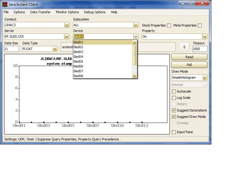
For example, using the Instant Client, one can select a 'standard' CDI property which will reveal all registered CDI devices:
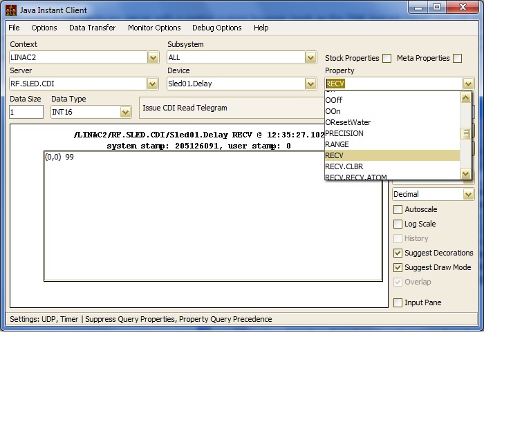
If one selects a non- standard or 'extended' property (i.e. a template field), the the devices offered are only those which apply to the selected field.
As a consequence, non-template devices are also registered as properties, with a device list of a single entry, namely itself also as device. These are known as 'extended properies' and provide a convenient multi-channel array of calibrated output data.
Any access using these 'extended' properties are mapped to the full CDI device name ('<template instance>.<template field>') and acces the CDI 'standard' property 'RECV.CLBR' (or 'SEND.CLBR').
A device server can access hardware data through CDI either asynchronously or synchronously. A simple example is shown below. Here, a contract for calibrated data for 100 monitor is initiated. Furthermore, the data type specified is "CF_INTINT", which will deliver an array of 100 integer-integer pairs, the first in the pair being the calibrated readback data, the second being the readback bus status.
Further aspects of hardware access are given in the section below.
Accessing CDI Hardware
As noted above, CDI hardware can be accessed 'in-process' via a device server if the device server itself initializes the CDI subsystem. Then all calls to the hardware talk directly to the CDI hardware layer.
A device server can also regard CDI hardware as 'extra-process' if a separate device server is used to communicate directly with the hardware. Although perhaps more convenient for debugging purposes, this second mode of operation introduces a network layer between the device server and the hardware as well as synchronization and latency problems. Where performance is critical, 'in-process' commmunication is to be preferred.
That being said, a useful tool (particularly in the hardware testing phase) is the CDI raw hardware server. This is a device server process which does nothing except read the CDI address database and offer the contents as a 'dumb' device server (i.e. no logic, intellegence, etc.). Nevertheless, some monitoring for alarms can be achieving by supplying an 'alarm watch' file, and local history archives can also be maintained via a local history configuration file.
The CDI raw hardware server is a binary executable called 'CdiHdwSrv.exe' in Windows or 'CdiHdwSrv' in UNIX.
Starting the hardware server without any command line arguments will cause the server to read the CDI address database and start the device server using default settings for server names and ports. Most settings are however configurable at the command line. Typing
CdiHdwSrv /?
at the command line gives:
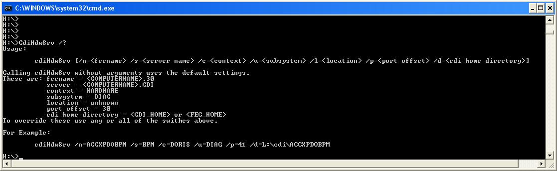
So an easy way to test hardware io is to use the CDI hardware server and the TINE instant client.
Once a server layer has been established, access to the hardware can be garnered by calling device '/localhome/cdi/<device name>' (in-process) or '/<context>/<server>/<device name> (extra-process) and the appropriate CDI property.
Hardware bus transactions can either be synchronous (using ExecLink() or ExecLinkEx()) or asynchronous (using AttachLink(), AttachLinkEx(), or AttachLinkEx2()). Typically, changing hardware settings (i.e. 'SEND' commands) will involve synchronous calls. Monitoring hardware settings will more than likely be asynchronous calls (involving a callback). One should be aware that using the asynchronous interface is much more efficient than synchronous polling, even if there is only a single client doing the polling! This is particularly true of CDI, where asynchronous calls are farmed out to extra hardware io threads, while synchronous calls are NOT!
Both synchronous and asynchronous calls can either specify a single device or a range or group of devices. When a single device is accessed, then the call's return code will essentially provide the hardware status of the device in question. Either the bus format can be used to access the device or perhaps a floating point datatype can be used if a calibrated result is requested. CDI will also let you access a group of devices by supplying a comma separated list as the 'device name'. Thus, with
device name = "Sled01.Delay,Sled01.On,Sled01.Off,Sled01.OResetWater,Sled01.X60VError"
a request for five values will return the readback values for all devices in the list. Likewise, CDI will also allow you to access a range of devices by delimiting the range endpoints with " - ", (blank dash blank). Thus
device name = "Sled01.Delay - Sled12.Delay"
and a request for 12 values will return the readback values for all devices in the range. One can also combine ranges and lists if necessary, always with the proviso that the number of elements requested should be equal to the total number of devices requested. As this is basically something only the server developer has to 'get right' it does not present any sort burden on client-side programers.
Of course, acquired a number of devices with one call is sometimes very efficient and practical, but does beg the question: "how does one know if one or more devices in the group have bus errors?". This answer here is to make use of a doublet (or triplet) format type when accessing the data.
A doublet type would include, say, CF_INTINT, CF_FLTINT, CF_NAME32INT, etc. If accessed in this way, CDI will fill in the first element of the doublet with the hardware readback value and the second element of the doublet with the hardware bus status.
A triplet type would include, say, NAME32INTINT or NAME32FLTINT, etc. If accessed in this way, CDI will fill in the name element with the device name, and the remaining pair with the readback and status values. This can be used to avoid any uncertainties regarding the actual device names contained in a range of devices.
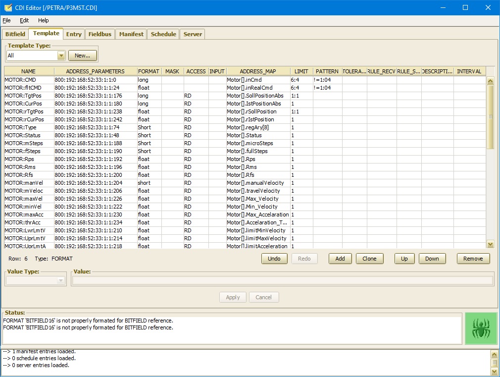
CDI Editor/Database Manager
This section will hightlight the CDI database manager and how to use it to make and edit CDI databases. One can of course use a spreadsheet editor such as excel to produce and edit a CDI address database. Such an approach is easy prey for copy-and-paste errors and has no consistency checking. A better approach is to make use of the CDI editor which allows you to either create a new CDI database or to edit an existing one. In any event, database entries which are illegal or inconsistent are trapped by the editor.
On three separate tabs you can enter one or more bitfields, one or more templates, and finally the CDI devices themselves along with their addresses. Logically you will want to fill in the bitfield information first, as it could be then made use of in the template definitions.
For example, under Bitfield you might have something like:
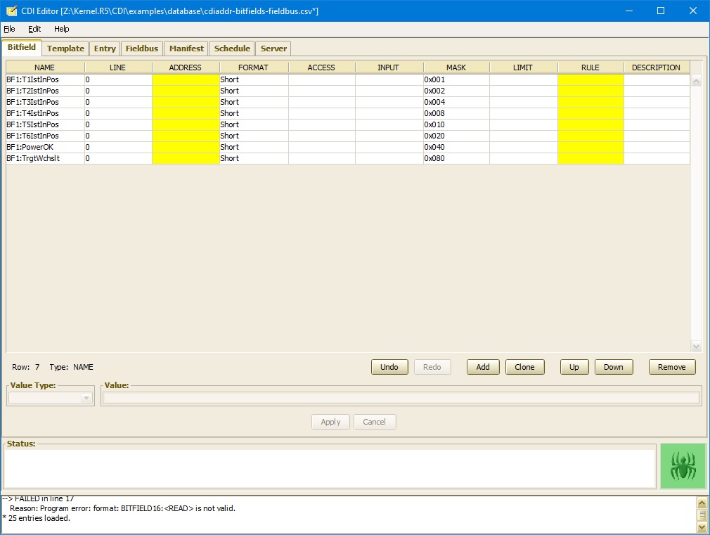
Under Template, one then might have something such as:
The specific devices are to be entered under the Entry tab:
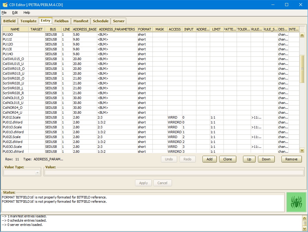
Any particular cell will know what set of allowed information can be entered in the cell and will notify the user of invalid entries. Note that an Entry which refers to a template should make a note of the specific template in the ADDRESS_PARAMETERS column.
Unknown columns which have been added outside the editor will appear 'shaded' so that the user is made aware of the fact that the information will not be read by CDI. In this way, accidental typographical mistakes can be easily made known to the user.
CDI Bus Plugs
The CDI manifest will instruct the CDI library which bus plug libraries to load upon initialization. The bus plug library must have the same binary name (case sensitive on UNIX) as entered into the manifest (however the extension ".dll" or ".so" should be omitted). CDI will then load the bus plug libraries in the order given in the manifest.
The bus plug should be written as a shared library and have a prologue which registers all applicable bus plug dispatch handlers. The prologue will be called by the operating system when the library loads. In Windows, the prologue is required, in that
BOOL WINAPI DllMain(HINSTANCE hInstDll,DWORD fdwReason,LPVOID lpvReserved)
is a required export from all DLLs. Initialization instructions should be included in when fdwReason == DLL_PROCESS_ATTACH. In UNIX, a routine of the form
must be included in the library code.
When the CDI library accesses an address it will have to know what bus to use and consequently what the bus plug is called, so a name must be assigned (this will be the bus name used in the CDI address file).
The bus name is assigned via any of the bus dispatch routines.
Initialization (optional)
The bus itself may have specific initialization steps to undertake, so a bus initialization function can be registered. This must be a function with the prototype
int initFcn(int busLine, int cdiLine, int numberDevices, char *parameterList);
Hence, the initializing bus line (the line number of this type of bus), the cdi line (the CDI internal line number), the total number of devices registered on the bus, and a character string containing any optional bus parameters given in the database. The bus initialization function (if registered) will be called by CDI once on inialization and receive all of these arguments and can process them in any manner necessary. The initialization function can be registered by calling cdiRegisterBusInitialization().
Cleanup (optional)
When CDI exits, the library will also call a bus cleanup function if registered. This might be used to free resources, etc. This must be a funcion with the prototype
int exitFcn(int busLine);
Thus, the bus plug will receive the bus line number of the bus which is closing down. The bus cleanup function can be registered be registered by calling cdiRegisterBusCleanup().
Filter (optional)
CDI can also make use of a bus filter function to prevent extraneous or irrelevant bus activity from interfering with desired bus traffic. If such a function is desired, it must have the prototype
int filterFcn(int *parameter, int accessFlag);
and will be passed the address parameter list and CDI access to use as a filter. Such a function can be registered by calling cdiRegisterBusFilter().
Scanner (optional)
CDI can also call a bus scanner function if registered. This can be a very useful diagnostic tool. As the nature of a bus scan depends strongly on the type of bus, the registered scanner function will basically deal with character string input and output and must have the prototype
int scanFcn(char *request,char *result,int resultBufferSize);
Therefore, when called, the scanner function will be passed a character string describing the request and deliver a character string containing the results of the scan (not to exceed the buffer size given). An empty 'request' or a 'request' containg the string "help" should return a list of availble commond strings. A bus scanner function can be registered by calling cdiRegisterBusScanner().
Handler (required)
The principal activity of the bus plug (the reason why it's 'there') will be to direct access to or from a CDI device to the appropriate bus address. This will involve providing the bus plug will all relevant information to complete the request. The bus plug must register a bus handler function which CDI can call to process the task. This will be a function with the prototype
and is registered by calling cdiRegisterBusHandler(). In the above, we see that a pointer reference to a single complex data structure is passed to the bus plug. This structure (the CDI request information block) is given in the CDI API documentation.
A bus plug is only required to register this function in order to be able to handle bus requests.
An example making use of the above registration functions is shown below for the case of a bus plug called (by default) "SIMULATE":
We see that the startup routines will be called either in the DllMain routine (Windows build) or in the Constructor (Linux Build). And that a bus "SIMULATE" will be registered by default. This bus plug name can be overriden via the environment variable CDI_SIMULATE_PLUG.
Examining the bus handler function in more detail, we might make use of the following example
An example of a bus scanner function might be:
This simulation bus plug can be substituted for any other hardward bus plug (so as to test communications) by ajusting the bus plug environment in the local bus manifest file.
For instance the following manifest file will load the CDI library cdiSimulate (cdiSimulate.dll on windows or libcdiSimulate.so on Linux systems) and set the environment variable CDI_SIMULATE_PLUG to CANSOCKET for the process, ensuring that this simulation bus plug registers itself as bus CANSOCKET. And thus an existing cdiaddr.csv address file will see its targeted bus when it is loaded.