A Few Words Up Front
The structure of the CDI database is beginning to stabilize so that a CDI database manager (wizard) can be written. At the moment the best database manager remains MS Excel. But there is no checking of name lengths, consistency, etc. so be very careful.
CDI is itself loosely coupled to TINE (dependency on the tine library). Remote access, or redirection of course are strongly coupled to TINE. It is important to pay attention to the current limitations regarding name lengths at the outset in order to avoid confusion later on. Namely, CDI device names can be up to 32 characters long. As the CDI layer is usually accessed via the TINE client API, it is important to make the distinction between accessing the local hardware with CDI (using context "localhost") and accessing the hardware remotely via TINE (using context "HARDWARE" for instance).
The device string passed in any CDI call can contain a group of CDI devices or a range of CDI devices. As just noted, each individual CDI device in the group can have a name length of up to 32 characters. If this call is made locally, there is never a problem. If this call is made over the net, the device name string has to fit into the transport headers of TINE release 4, which can accomodate a string up to 1024 characters.
Thus, under extreme cicrumstance (a very long device train) even though the call would have succeeded locally, there might be some truncation of the device name string passed before it reaches the CDI subsystem on the target host. Please, please keep this in mind when you go about assigning names to devices and attempt to address a device group over the net.
CDI keeps a log file which will be found in either the CDI_HOME or FEC_HOME directory (see Step 1, below). If something doesn't work, it is always a good idea to consult this file so see first if there are any clues there as to the reason for failure.
This Tutorial
This tutorial is designed to demonstrate how you construct a CDI database to access the local hardware, assuming that the necessary CDI bus plug(s) is (are) available.
This tutorial does NOT cover or in any way illuminate how you can write a CDI bus plug for an as yet unsupported hardware BUS.
Currently supported bus plugs include those for SEDAC (various interfaces), CAN (various interfaces), RS232, TwinCat (Beckoff), Siemens PLC. The bus plugs exist for both Windows and Linux in each case except TwinCat, where the Beckhoff interface is Windows specific.
This tutorial will make use of a simulation bus plug for the SEDAC variant "SEDPC" (in-house DESY Serial bus). Generally speaking, the specific bus used in the CDI databse is not particularly relevant as far as the interface to CDI is concerned. However certain optional column entries in the CDI database such as "PATTERN" or "ADDRESS_MAP" are in turn not relevant for "SEDPC" and are hence not included in what follows. The "PATTERN" column plays a much stronger role in with the RS232 bus plug, and the "ADDRESS_MAP" column is particularly important for the TwinCat bus plug. These may become the subject of a future tutorial, but are not discussed here.
Step 1: CDI environment
When the CDI subsystem starts it will look for startup files inside the directory pointed to by an environment variable. The first choice is "CDI_HOME". If this is not set, the second choice is the tine environment variable "FEC_HOME". If this is also not set, then the working directory is scanned.
Check to see if the environment variable "CDI_HOME" is set (probably not). Now check to see if the environment variable "FEC_HOME" is set (maybe).
Now decide. If you want to keep the CDI hardware database files in a separate directory structure than the tine server, then set CDI_HOME to a directory of your choice. Or continue using FEC_HOME to keep the hardware relevant database files together with the server relevant database files.
Recommendation: See where FEC_HOME is pointing to. This might be something like "C:\tine\database\server\". Create a CDI_HOME environment variable and make it point to a neighbor directory, for instance "C:\tine\database\cdi\".
Step 2: CDI manifest
Now create, in the CDI_HOME directory (or FEC_HOME directory), a single text file called cdimf.csv. This will be a "comma separated value" file containing the CDI manifest. As your tutorial computer is (probably) not connected to hardware, we will be using a simulator bus plug for our CDI tests. So the contents of your cdimf.csv file should look like the following:
This is a simple text file and can be created with any editor, but in the case of csv files, it is sometimes more expedient to use 'Excel' so that what belongs to which column is readily visible. But when using excel, remember to store the file is ascii mode and MAKE SURE the international settings for your machine do not try to use a comma for a decimal separator (as is common in German windows) as this will wreak havoc on the csv parsers!
The relevant column in this simple manifest file is "LIBRARY". Our simulator bus plug is a library called cdiSedPcSimul.dll (windows) or libcdiSedacSimul.so (unix) and will be loaded when the subsystem starts. This simulator bus plug simulates "SEDPC" which needs a bus environment, therefore the optional column "BUS_ENV" is also present (although not necessary for the simulator).
This manifest file serves only one purpose and that is to signal the CDI subsystem as to what hardware is connected to "this" computer, namely which bus plugs need to be loaded.
Step 3: cdiaddr.csv, the hardware database
Now create a CDI address file in the same directory. This is also a csv file and should be called cdiaddr.csv.
To begin with, fill in this file with 4 devices with just the basic information according to the following example:
- Note
- The csv parser will not care which order the columns appear in. The first non-commented line will be interpreted as the csv header.
The columns used in this example are not optional. The first two columns identify the hardware address with a hardware device name (which should of course be unique within the context of the database).
The "BUS" column specifies which bus should be addressed when contacting this hardware address. In this case, all of our entries will have "SEDPC" in this column. This must be a bus that has been loaded according to the manifest (otherwise a bus error will ensue). In our case, when cdiSedPcSimul.dll loads, it registers itself as a bus named "SEDPC".
The "LINE" column specifies which bus line is to be addressed. CDI can handle each line independently, but for our purposes, we will pretend that all devices exist on SEDPC line 1.
The "ADDRESS_BASE" column specifies the bus specific base address. The address is parsed according to
<base address>.<sub address 1>.<sub address 2> ...
The "ADDRESS_PARAMETERS" column specifies specific address parameters associated with the device. The parameters are parsed according to
<addr param1>:<addr param2>:<addr param3> ...
In the case of SEDPC this translates into <crate address>.<sub address> for the ADDRESS_BASE and
<read register>:<write register>
for the ADDRESS_PARAMETERS. In the above table we have specified the same crate for the 4 devices and different sub addresses and have passed a "0" for the read register and nothing for the write register. CDI will simply pass the address parameters on the bus plug, and the SEDPC bus plug will use the read register for the write register if not explicitly given.
Other busses such as CAN or RS232 have a slightly different address scheme, but nonetheless a scheme which fits the same address database. Bus plugs for TwinCat use a combination of the ADDRESS_BASE and ADDRESS_PARAMETERS columns and the otherwise optional "ADDRESS_MAP" column to specify an address register.
Finally the "FORMAT" column is formally optional but it is strongly advised to specify this information. Specifically this gives the bus format for reading and writing data to and from the hardware for the specified device.
The bus plug of will in many cases know this information out of hand. However if the caller's requested format is not identical then a decision on how many values to read and how to calibrate needs to made by CDI, which is expedited by knowing this information up front. Querying this information from the bus plug is in some cases sufficient but for others not. For some busses, such as CAN, the base format is device specific.
Step 4: Raw Hardware Server
Now open up a command prompt and type CdiHdwSrv as shown below
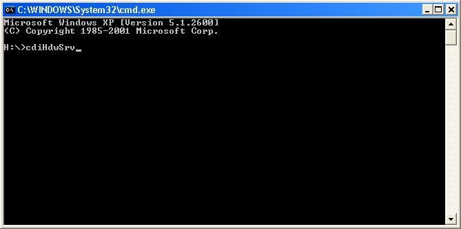
This should start a so-called "raw" hardware server, which will read your database and offer its contents as a tine server in the context "HARDWARE" with the device server name of <COMPUTERNAME>.CDI
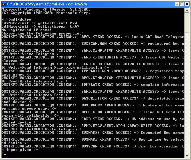
You should see something like the following:
So open up the instant client and browse to the Context "HARDWARE" and look for your hardware server. You can see what your computer name is by opening up another command prompt and typing "set COMPUTERNAME".
You should see the four devices "HDW1", "HDW2", "HDW3", and "HDW4". If you have a look at the properties, you will see a number of properties which give information (such as "BUSNAME", "BUSADDR", "BUSERRORS", "DESCRIPTION", etc. and a number of properties which initiate actions on the bus, such as "SEND", and "RECV", as well as atomic operations such as "SEND.RECV.ATOM", or "RECV.SEND.ATOM".
Spend some time investigating these properties.
The first thing you will notice is that you always read "0" when you access the "RECV" property. That's because the simulator doesn't have any contents inside its simulation buffers. So you should choose a device (say "HDW1") and issue a "SEND" command by first opening up the input panel, specifying "write access" and sending some value to the bus. Now you should be able to read it back with a "RECV" command.
You can also test the atomic operation "SEND.RECV.ATOM" in this way as well.
Also note that CDI provides a "BUSSCAN" property. The behavior of this property is bus specific, however access to this property always occurs via strings. Try accessing this property with a simple "Read" and you will see a list of the supported BUSSCAN commands, such as "getlines", "getcrates", etc., all relevant for SEDPC. To access any of these, you will have to open up the input panel on the InstantClient and supply the specific query as an input text string. (Note: this does NOT require WRITE access; a simple READ will do). Some queries, such as "getcrates" require input. You can separate the input tokens with the standard CDI tokenizer character ":", such as "getcrates:1" etc. Spend a few moments trying this out.
Step 5: access
Now we're going to add another column to the database. Specifially, we're going to limit the allowed access to certain devices. So add a column called "ACCESS" to your database, and fill it with the information given in the example below:
CDI will accept "RD" or "READ" to specify READ access and "WR" or "WRITE" to specify WRITE access. If the entry is empty, then everything is allowed, which is formally equivalent to "READ|WRITE" or "RD|WR". Note the logical OR "|". This is not the same thing as "READWRITE" ("RDWR") or "WRITEREAD" ("WRRD"). (No OR character). This latter will require an atomic operation for the call to complete successfully.
So save your database and restart the raw hardware server. Now try to "SEND" something to device "HDW2" or to "RECV" something from device "HDW3". To access "HDW4" you will have to call "SEND.RECV.ATOM" to be successful.
Step 6: write input
Now let's add another sometimes important column to the database and see how it interacts with the "ACCESS" column. This will be the "INPUT" column which specifies the default data to input with an atomic "WRITE" call. Add this column according to the example shown below:
You'll note that we have specified the value "51" in only one place, namely for device "HDW4", which is the device flagged as "WRRD" only.
Now restart the raw hardware server and issue a simple "RECV" command for "HDW4" and you'll be able to read the value "51" without "SEND"ing it yourself.
This "trick" is used to great advantage for those hardware modules that require an address register to be first written to the hardware module prior to a read command.
Step 7: read/write Offsets
Now we'll have a look at the address parameters associated with a CDI hardware device. Edit the "ADDRESS_PARAMETERS" column in your database so that you supply different "READ" and "WRITE" offset parameters, according to the following example:
You will note, that we have added a ":16" to each of the addresses for "HDW1", "HDW3", and "HDW4". This will inform CDI to identify the device "HDW1", for instance, with crate 16, sub address 32 on SEDPC line 1, but to use the address offset "0" when reading from this module and to use the address offset "16" when writing to this module.
We did not bother specifying this information for "HDW2" because it is flagged as "RD" only.
If you now restart your raw hardware server, and write something to an address or "RECV" something from "HDW4" you will now read back a "0". Why? This is because the SEDPC simulator actually keeps track of address offsets, so you are putting a number in a different location than where you are trying to read it back.
You may possibly want to revert back to the previous database or otherwise specify "0:0" instead of "0:16", if you want to see the "fruits of your labors."
Step 8: limits
Now we'll see how to tell CDI to restrict the amount of data accessed from the bus per call. This will involve adding a "LIMIT" column to the database. So please modify your database to follow the example below. Note that the write offset "16" has been replaced with "0" so that the bus plug simulator will return what we have written.
For the first two devices "HDW1" and "HDW2" we have limited the size of a "RECV" call to 8 values. For "HDW3" and "HDW4" we have specified the read and write limits independently as "0:1" and "1:1" respectively.
Now restart the raw hardware server and try to read more than 8 values for "HDW1" with the instant client. You should see that the call is refused.
Step 9: rules
Now we are going to add a "RULE" column to the database and see how CDI handles calibration rules. So modify your database so that it looks like the example below:
Note that we have modified the ACCESS for "HDW2" so that both "RD" and "WR" are allowed. This will let us test the calibration rules in force.
CDI will apply the calibration rules in the order (left to right) they appear. The rules are separated by the CDI tokenizer ":", and include addition/subtraction (+,-), multiplication/division (*,/), exponentiation (^), log (L), modulo (%), shift right (>), shift left (<), signed (S), unsigned (U) and message (M).
So far we have applied calibration rules to "HDW1" and "HDW3" above.
Now restart your raw hardware server and test the calibration as follows.
Accessing the properties "RECV" and "SEND.RECV.ATOM" will behave as before, returning the value read from the bus (no calibration rules applied). To see the calibrated value, you should access "RECV.CLBR" or "SEND.RECV.CLBR". In our case, accessing "RECV.CLBR" for "HDW2" and "HDW4" will be revealing.
Calling "RECV.CLBR" for "HDW2" will return "30" since the initial data contents for this device is "0" and "(0 + 10) * 3" = "30".
Calling "RECV.CLBR" for "HDW4" will return "-32720" if you don't pay attention to the calling data type in the instant client, this is because it's probably resting on "INTEGER" (i.e. a signed short integer). Changing this to "LONG" or "FLOAT" and repeating the call will return 32816 (i.e. 51 + 32765).
Repeat this test by changing the input value "51" to "-51" in the address database for "HDW4":
Now restart the hardware server and issue a "RECV.CLBR" command for "HDW4" and you'll see the value 98250 returned, which is perhaps not what you expected (-51 + 32765 = 32714). This is because the value "-51" converted by default to an unsigned value (65485) prior to calibration. The bus plug has no way of knowing the signed-ness of the data by itself.
If you modify the address database rule to apply the signed rule before addition you should get the value you expect.
Last, but not least, let's apply a "message" rule to "HDW1". This rule will signal CDI to return a text message dependent upon a matching value or not. To see how this works, modify your cdiaddr.csv database according to the following example:
You will note that we have added the rule M16<OKAY><NOT OKAY> for the device "HDW1". The "M" signifies a message to be applied to the data read. The "16" is the target value. If the read value to be calibrated matches "16" then the message string "OKAY" is applied to the data, otherwise "NOT OKAY" is applied.
Try this out. If you simply read "RECV.CLBR" you will still see "0" unless you remembered to change the requested data type to "NAME32" (this is mandatory). Once you specify type "NAME32", you should see "NOT OKAY" as the returned string. You will have to "SEND" the value of 16 to "HDW1" before you will be able to see "OKAY".
The message calibration rule can be used in conjunction with the signed/unsigned rules and like all other rules will be applied after any optional data mask is applied. A data mask is applied by supplying an optional column "MASK" and providing a bit pattern (in hex) to be applied to the relevant data. This will not be covered in this tutorial, but is straightforward enough for you to try out by yourself (just add a column "MASK" to cdiaddr.csv).
Step 10: description
Add another column to your database called "DESCRIPTION". You can fill this with a 64-character description of the device entry. For instance:
Now restart your hardware server and access the "DESCRIPTION" property.
Step 11: templates
So far we have been dealing with a rather simple database with 4 devices. More cases are of course much more complex. In particular, hardware modules will typically have repeating patterns which might require tedious copy-and-paste activity if not for CDI templates.
So let us now assume, that the hardware devices we have entered "HDW1" to "HDW4" all refer to a certain kind of hardware device module called (for want of a better example) "SEKI".
Each SEKI module has 4 address offsets which refer to different things about a SEKI. So rather than making 4 X 4 entries in our database (this could be a lot worse!) we can simplify life be first registering the SEKI module as a CDI TEMPLATE and marking each of our hardware devices a SEKI module.
To see how this is done, modify your database according to the following example:
The first four lines specify a "SEKI" module and flag the bus type as "TEMPLATE". CDI will first scan the database for all template entries and register them. The template entries all have a device name according to the pattern <template name>:<register name>. Similarly, the template base address is always "0" and the address parameters supply for instance the read/write offsets (e.g. 20:20).
Note, again we are using the same read and write offsets so that the simulator bus plug will return the value written when a read request is made. We have also allowed all template registers to "RD" and removed the access flags from the individual device entries.
The hardware devices "HDW1", etc. now give the base and sub addresses for the specific module but then reference the template for the module sub-structure.
Also, note that when using templates, entries such as "RULE", "LIMIT", "INPUT", "ACCESS" all refer to the the values given in the template.
Try this example out by restarting your raw hardware server. If you now look in the instant client you will see that the device list now looks substantially different. Namely, our original "devices", "HDW1", etc. now only identify the module, the devices now reflect the substructure in the template, e.g. "HDW1.sts", "HDW1.soll", etc.
Step 12: multiple reads from CDI
With CDI you can read several devices at once (atomically) by specifying the devices individually or as a range. So far in our tests, we have been looking at a single device. But you can for example make the following call (where you supply by hand the device name string in the instant client)
- device name "HDW1.hv - HDW4.hv"
- property "RECV"
- Data size = 4
You will see a list of 4 values. You can also specifiy the data type as "NAME16II" or "NAME16FI" which will return the same 4 values, as well as other relevant information, namely the device names returning values, and the status of the individual calls on the bus. Specifying a data type of "INTINT" or "FLTINT" will likewise return value-status pairs.
Step 13: Interface to the Device Server
It is important to realize that the CDI raw hardware server can do nothing more than provide an interface to the hardware configured inside the CDI database. While it might occasionally be true that this minimal interface in some cases provides a sufficient device server interface, this will rarely be the case. The raw hardware server should be viewed as a tool to test the configured hardware. Indeed, the raw hardware server does absolutely NO background io by itself!
In general you will be putting together a device server, whose device names represent real device modules or locations and whose properties represent attributes or actions on these devices, and not the CDI address registers in the CDI database. In some cases the final data to be delivered when a property is accessed depends on more than one CDI hardware "device". For instance the PT100 temperature readouts depend on reading raw data from temperature modules and calibrating these data based on calibration factors read from other CDI address registers.
Furthermore, a device server is likely to offer properties (i.e. methods) which start processes or otherwise involve actions beyond a simple readout of address registers.
So a device server becomes a "client" to the CDI hardware, and the general TINE client API is used, with the full range of data acquisition features, to access the hardware. Where you were once using hardware specific APIs (with calls such as SedacRead()) you now will be using TINE links, either asynchronous or synchronous. The asynchronous calls involve a CDI contract to perform the operation asynchronously on a separate thread and notify the caller via a callback routine when the operation is finished.
So as an exercise, you can use the TINE device server wizard to provide a skeleton for a device server and edit the code, so that the hardware io is provided by the CDI subsystem.
- Use the device server wizard (chose your favorite platform) and create a device server called "SEKI" (or rather "<your name>.SEKI" so as to avoid name collisions) and with properties "Status", "Power", "HV", "TargetValue", and devices "Unit1", "Unit2", "Unit3", and "Unit4".
- Start a background task which reads "HDW1.sts - HDW4.sts" with property "RECV.CLBR" (4 NAME32 values) asynchronously with a call to the AttachLink() method. Assign the incoming data to a global buffer and make this same data available from the device server via property "Status".
Example: AttachLink("/localhost/cdi/HDW1.sts - HDW4.sts","RECV.CLBR",dout,NULL,CA_READ,statusCallback,CM_POLL);
- In the same background task, read out "HDW1.pwr - HDW4.pwr", etc. and connect the readback values to the other exported properties. Now reading these values from the device server always returns the last read value from the hardware buffer.
- Allow the setting of properties "Power" and "TargetValue" for a single device and connect the set value to a "SEND" call to the appropriate cdi device.
- In the background task, check the readback values for possible alarm states and set alarms appropriately.
Multiple Databases
Under some circumstances it might be desirable to have more than one server on the same host computer making use of CDI and using different databases. One way to achieve this is to place the relevant database files in specific directories and to set the CDI_HOME variable to point to the appropriate directory within a shell script prior to launching the individual server processes.
Another alternative is to provide a database hierarchical structure within the CDI_HOME directory according to <CDI_HOME>/<fecname>. The CDI subsystem will first attempt to locate the cdiaddr.csv file at this location before resorting to looking directly under <CDI_HOME>.
Note that the CDI manifest file is always located in <CDI_HOME>.