The TINE Post Mortem/Event-based Archive System will be described below. We note at the outset that the adjective "Post Mortem" by itself is in this context something of a misnomer as the system can be used to record snapshots of events of any nature and not just 'post mortem' events where the implication would be that something 'terrible' has just happened, for instance: 'you just lost the beam'. It could be that the event in question is a positive event, more like: 'you just injected beam'. In such cases it's desireable to store a snapshot of the relevant machine parameters (machine optics, current orbit, etc.) at that time. A scan of 'injection' events over a time range (say, the past week) would then tell you precisely when beam was injected and you could easily examine the stored information at those times.
Needless to say, the TINE Post Mortem System does indeed get the most use following real 'post mortem' events (a magnet quench, RF trip, etc.), and we shall show examples below.
Event-based archives
We must first make clear the distinction between 'Event-based' archives and 'machine parameter' archives. The latter is what is usually regarded as an archive system and is described in the discussion on the TINE Archive System. Namely, the designated parameters of the machine are archived versus time with possible filtering on machine states, data-change tolerances, etc. To be sure, it is possible to override the filtering mechanisms in place and insert machine values into the archive according to an event, but this is not what is meant here by 'event-based' archives.
Event-based archives are archive snapshots which are based on "scripts" specifically targeting the event in question. In particular, post-mortem data frozen in the hardware, which are normally not found in the machine parameter archive can be collected. This is typically a set of transient data sampled on a very fine time raster centered at the time of the event. In a similar vein, data kept in short-term storage in a server's local history repository at a much higher sampling rate than on the central archiver can be retrieved and stored in association with an event. Event scripts can as well trigger other activities by issuing commands to other servers, etc. The event script is also designed to collect data (in principle) from different sources and identify them with a single event. For instance, with a 'beam injection' event the machine optics, orbit parameters, bunch currents, etc. can be collected precisely at the time of the event, irrespective of what has been stored away in the machine parameter archive (which may have filtered out some of the relevent parameters at the time of the event).
Trigger Scripts
The afore mentioned event archive scripts are themselves nothing more than flat .csv files containing the step-wise data acquisition instructions. See "Event-Archive Database" below.
In general, you will not need to get your hands dirty with the actual form these scripts take, as the event archive database manager is a powerful tool which allows editing and appending all manner of entries in the event archive database. Essentially all of the database management as well as transient recorder viewer configuration management is handled directly via this tool, obviating the need to even look at any individual file. Nevertheless, we show here (for documentation's sake) examples of the 'ingredients' which make up the event archive database repository.
Consider the example below of an event 'script' which retrieves 16 channels from an rf-feedback transient recorder:
In this case, each 'step' of the script is a data acquisition instruction containing the Device 'Context', 'Server', 'Property' and 'Device' to acquire. The post mortem server allows the data so acquired to be stored under alternate 'Server' and 'Property' names if desired, hence the 'ArchiveServer' and 'ArchiveProperty' columns.
The 'Size' and 'Format' columns give the data size and format to use to make the TINE call. The 'Access' column indicates primarily the TINE access mode and is typically 'READ' as seen in the above example. But this is not always the case as we'll see below. The remaining columns are not used in the above example so we shall defer their discussion for the moment, except to point out that the 'Scale' and 'Shift' column can be used to massage the data after they have been acquired and before they have been committed to disk.
The above example consists of aquiring 16 different channels of transient recorder data plus data headers specific to these transient recorders. Noting that a device name can always be replaces by its corresponding device number (preceded by a '#'), the above script can be simplified considerably by writing it follows:
Now consider a somewhat more complicated case of storing the beam loss monitor readings following an abrupt beam loss. We'll assume that the data have been frozen in hardware, and that the monitors can be read out individually in either a short term mode (in 5 millisecond time bins) or a long term mode (1 second time bins), but that the hardware needs to receive a signal to switch modes. Consider the following script:
Initially the property 'MODE' is set to '1' which comes from the 'Value' column which is used if the 'Access' is 'WRITE' or 'POLL'. Then the property 'CYCLECOUNT' is 'POLL'ed until the return 'Value' is '0', at which time it is assured that all monitors have been switched to long term and have loaded their hardware. The polling cycle 'Wait's 1 second before polling again and will cease polling after a 'Timeout' of 100 seconds if the polling conditions (of 'CYCLECOUNT' == '0') have not been met. Then the property 'RAWLOSS', which obtains a monitor's ring buffer from the hardware, is called on behalf of monitor #1 to #282 inclusive, storing the returned data under the name of property 'LLOSS'. The next 2 steps switch the 'MODE' to '0' (short term) and ensure that the polling conditions have been met after which the property 'RAWLOSS' is called again for all monitors and stored under the name of 'SLOSS'. Finally, a snapshot of the final reading for the entire series of monitors is obtained by 'READ'ing the property 'AVELOSS'.
More complicated archiving scenarios are also possible.
The scanned columns in a trigger script consist of the following:
- "CONTEXT" is the context of the target (option: if omitted, the event archive server's context will be used.
- "SERVER" is the device server name of the target (historical alias: "TAG"). This can only be empty if the row contains a "WAIT" instruction.
- "PROPERTY" is the device server property of the target. This can only be empty if the row contains a "WAIT" instruction.
- "DEVICE" is the device server device name of the target.
This can only be empty if the row contains a "WAIT" instruction. - "ARCHIVESERVER" is the "stored" server name when the call completes. (historical alias: "ARCHIVETAG"). In some cases the server name used to acquire the data needs to be modified or adjusted when stored. This parameter can be used to achieve this. If omitted, the "SERVER" name information is used.
- "ARCHIVEPROPERTY" is the "stored" property name when the call completes. In some cases the property name used to acquire the data needs to be modified or adjusted when stored. This parameter can be used to achieve this. If omitted, the "PROPERTY" name information is used.
- "SIZE" gives the number of the data elements of obtain with the call (acording to the format specified. This can only be omitted if the row contains a "WAIT" instruction.
- "FORMAT" gives the data format of the data to obtain with the call. This can only be omitted if the row contains a "WAIT" instruction.
- "ACCESS" gives the data acquisition access to use with the call. Possible values are:
- "READ" : the acquisition is a synchronous READ operation
- "WRITE" : the acquisition is a synchronous WRITE operation
- "POLL" : the acquisition involves synchronous POLLING until either a MATCH condition or a SERIES condition is met.
- "MATCH" : the acquisition involves polling for a matching value (given in the "VALUE" column).
- "WAIT" : the acquisition should wait for the number of seconds given.
- "SETNUM" : the acquisition should use the returned data to fix the data size of the next call.
- "PREALLOC" : the acquisition should use a pre-allocated buffer (used in conjunction with "SETNUM").
- "FORWARD" : the acquisition should obtain the data and forward the results on the the next step.
- "SERIES" : the acquisition represents a series of acquisitions, the number given by "VALUE" and the time between acquistions given by "WAIT".
- "MONITOR" : the acquisition should start a monitor link with characteristics given by the "MONITORMODE" column. If omitted, "READ" is assumed.
- "WAIT" gives the number of seconds to wait following the call (default 0).
Can be used in isolation as a barrier between archive retrieval instructions. Optional (can be omitted). - "VALUE" an (optional) integer value used for instructions to "WRITE" data or to "POLL" data for a matching target value. Optional (can be omitted).
- "TIMEOUT" gives the number of seconds to wait when polling a target for a matching value. (default 1) If the timeout is surpassed, then the polling step is aborted. Optional (can be omitted).
- "SCALE" gives a floating point value to use to scale the acquired data (default is 1.0). Optional (can be omitted).
- "SHIFT" gives a floating point value to use to shift the acquired data (default is 0.0). Optional (can be omitted).
- "MONITORMODE" gives the acquisition mode to use for monitor calls. This can be any of the possible TINE transfer modes in combination with mode flags (default is "TIMER"). Is only scanned when "MODE" is "MONITOR".
- "MONITORRATE" gives the monitor rate in milliseconds (default is 1000); used only in conjunction with "MONITORMODE". Optional (can be omitted).
- "MONITORTIME" gives the monitor duration (in seconds!) for the data acquistion step. After the input number of seconds is surpassed (default is 600 seconds) then the monitor is halted. Optional (can be omitted).
- "INPUTFILE" gives the name of an extra database input file to be read and parsed for input data which is needed in the data acquisition step.
- "INPUTFORMAT" gives the format data type of any input data the data acquisition step needs (default = CF_INT32). This is used only if the "INPUTFILE" entry points to a data input file.
In the example above, there are 282 beam loss monitors which have been stored under a device number rather than a monitor name.
At the presentation level, it is in general much more desireable to work with names than numbers. So the question remains as to how we bind the device names to the numbers which have been stored. This is accomplished by supplying a device list to the post mortem server. In the above case, the beam loss monitors are obtained by making calls to the device server 'HEPBLM'. So if the post mortem server sees an initialization file 'HEPBLM-devices.csv' it can then know how to bind the associated module names with their numbers. This scenario of course only works if the device name to device number binding is quasi-static.
In any case, the data obtained via the event-archive scripts are stored along with their calling parameters in a binary formatted event file in the appropriate repository. The binary file will have a name given by the event number (in hex) followed by an extension signifying the type of event. The event number is generated by the TINE 'Event' Server and is typically the UTC time (seconds since Jan 1, 1970) of the event.
The contents of an event file are stored as follows
- Version - 16 bytes char string (storage version = TINE version)
Followed by (pro stored record):
- Context - 32 bytes char string
- ServerName - 32 bytes char string
- Property - 64 bytes char string
- DeviceName - 64 bytes char string
- Tag - 16 bytes char string (structure tag)
- status buffer - 32 bytes char string (short status string)
- size of call - 4 bytes int32
- data format - 2 bytes int16
- status - 2 bytes int16
- scale - 4 bytes float
- shift - 4 bytes float
- data buffer - N bytes according to format and size
Thus, a request to the post mortem server for data will end up opening a session according to the event in question, and the corresponding event file will be scanned according to the storage format shown above until a matching Device Server, Property, and Device Name is found.
Header Files
These are the 'basics' behind data retrieval from the post mortem server. In addition the post mortem server can return transient recorder specific header information. This is information as to range setting, engineering units, sampling rates, comments, etc. In some cases, such as in the HEPBLM example above, this information is known a priori and can be read during the initialization of the post mortem server, for example by reading a 'header' file, in this case BLM-header.csv:
Note that the header file refers to the event 'Server' name BLM and contains all pertinent information for all entries making up the event. See the discussion below on the Event-Archive Database. It is important to realize that different events (and hence different event 'Servers') might make use of the same device servers and devices but need to use different header information. In some other cases, the corresponding transient record headers are dynamic and need to be obtained and stored with the event.
In either case, a transient recorder header has the following structure:
Event-Archive Database
The interface to the Event data is entirely managed by the post mortem server. The post mortem server is then responsible for handling triggers to acquire new data and to satisfy all client requests for pulling out stored data. The Event-Archive database consists of the configuration database and the data itself.
Primary Database
The configuration database is made up of flat, human-readable .csv files at three layers. At the top layer, the server consults the file "pmArchiveList.csv" to determine the list of event archive sets it has to manage. This file fixes archive sets with data repository locations, script files, trigger parameters, etc. As an example:
The column Trigger identifies at the same time the archive 'event context' and the name of the event archive script file. The column Extension fixes the file extension to be appended to all ensuing post mortem archive files and is also used in the data repository hierarchy. The column Record is simply a flag which indicates whether or not this particular archive set should record each successful archive with the event server. Event archives which do not involve 'post mortem' data usually do not record themselves with the event server. The column Depth indicates (if > 0) the allowed time in months to maintain the event archive. If this value is 0 or not given, then the event archives are maintained forever unless officially removed. The column Forward indicates an optional server end point (context and server name) to which the incoming event notification should be forwared (a secondary event server for instance).
Looking at the first entry in the example above, we see that the trigger 'mhf_slsr_trc' will record itself with the event server following each post mortem event. The archive context is 'mhf_slsr_trc' which means that 1) the trigger to start this kind of post mortem archive is 'mhf_slsr_trc', 2) there is a local file called 'mhf_slsr_trc.csv' which is the event archive script to be followed after the trigger, and 3) queries for numbers and time of events pertaining to this category need to specify the event trigger context 'mhf_slsr_trc'. The event data is stored in the repository residing at '../CACHE'.
The script file 'mhf_slsr_trc.csv' follows the structure shown in the examples above in the Event-based Archive section. The set of event scripts (plus associated header and device files) make up the second configuration database layer.
We note that the individual script files may contain references to input files, if there is a non-empty InputFile column. If present an additional input .csv file will be consulted to provide input data to be sent with the TINE call. Such data input files make up the bottom layer in the configuration database.
Data stored in the repository has a hierarchical structure beginning at the location specified in the 'Source' column of the pmArchiveList.csv file. Basically the hierarchy looks like (assuming the 'Source' is '../CACHE' as in the above example):
../CACHE/<YYYY>/<MM>/<'Extension'>/<individual files>
Possible columns in the primary database file pmArchiveServer.csv include the following:
- "TRIGGER" (alias "NAME") gives the name of the trigger which causes the event 'script' to run and at the same time provides the name of the event script.
- "EXTENSION" gives the event file extension to be appended to all stored event files.
- "RECORD" (optional) gives a binary indication of whether the event trigger should be forwarded (recorded) to the site event server (default = 0).
- "DEPTH" (optional) if greater than 0 gives a depth in months to keep event archives (default = 0).
- "SERVER" (optional) provides a server name to which to forward the event trigger.
The maintenance of the post mortem database is facilitated by using the Event archive database manager as shown in the figure below:
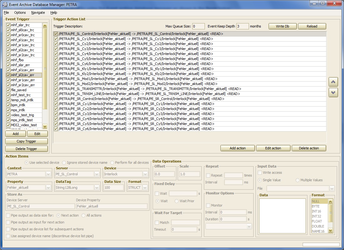
One can add or edit existing event 'triggers', which are identified by a character string (maximum 64 characters). Selecting a trigger enables one to add or edit the 'Trigger Action List' (i.e. the trigger steps) which appear as 'Action Items' in the lower left panel. Action Items can in principle involve more 'complicated' data operations (or require input data, etc.) than simply acquiring a data set from the designated server as a simple read operation. Specific data operations can be given in the Data Operations Panel at the lower right.
Configuration Management
The Post Mortem/Event Archive Server is also a repository for transient recorder configurations to be queried and used by the transient recorder viewer. The configuration repository resides under ../CACHE/CONFIGS, specifically in ../CACHE/CONFIGS/TRC for the available transient recorders. This 'viewer configuration' repository is in analogy with that of the "Pre-defined Configurations" for the TINE Archive System.
In this case a primary file 'triggers.csv' provides the overall configuration information and must be present if the post-mortem archiver is to be able to provide configuration information for the transient-recorder viewer. An example is shown below:
Here we see that transient recorder event triggers such as "dotrcrfnl" provide descriptions (which are used in browsing) as well as structure files (in this case "DorisNL.csv") which provide the browseable information to use in the transient recorder viewer. In this example:
These configurations are likewise managed by the event database manager shown above. If one selects the menu item options -> 'Event Viewer Configurations', one is presented with the following viewer configuration manager, which allows easy trigger browsing and channel selections for the transient recorder viewer.

Event Server
In principal the post mortem/event archive system can consist of one or more 'stand-alone' post mortem archive servers, where 'events' happen and trigger event archives, which remain uncorrelated and un-sycnhronized among themselves. Nonetheless, it is sometimes desireable to have other information at hand as to "what triggered at the same time?," i.e. "what belongs together?", "what triggered first?", etc. and to be able to browse a list of related events, even when the post mortem data is stored on diffent servers.
To this end, a TINE Event Server exists and is responsible for assigning event numbers and managing an event database where the 'contributers' to an event are stored.
An event number is, as mentioned previously, the UTC timestamp at the time of the event. The event server assigns this number according to the first received event trigger of a new event set. All subsequent triggers are deemed to belong to the same event if the triggers fall within an event 'window' of 5 seconds (adjustable) of the initial event, and a request for an event number within this window will receive the UTC timestamp of the initial trigger.
Furthermore, the event server will, according to its configuration, forward event triggers to associated post mortem systems, noting the origin of the initial trigger. The post mortem server receiving such a forwarded trigger can then decide to accept or reject the trigger based on whatever other criteria it needs. It is frequently the case that the other subsystems would have triggered (or were in the process of triggering) an event anyway. Note that a 'double trigger' within the event window is harmless.
An event is identified via an 'event code' and this is passed along with every event trigger. In this way, a post mortem server can decide the relevance of secondary triggers. In addition, each post mortem server has an identity which is passed along in all secondary triggers.
The interplay between a TINE post-mortem server and the TINE event server is decided by the 'Record' flag, as alluded to in the above sections. That is, a non-zero entry for this value in the 'Record' column of the pmArchiveList.csv will ensure that the such events are recorded with the event server. Events non so flagged will remain local to the corresponding post-mortem server.
Thus it is possible to browse among the 'site-wide' events by querying the event server for the number of events of a certain type between two time end-points. Then one see who participated in any individual event.
Examples
This section is under construction
A generalized event achive viewer allows simple event browsing where a given context is navigated to, providing an event list over the selected time range (default 1 year). The selected event provides a list of stored devices and properties which can be retrieved along with their event headers (if any) and displayed.

Event analysis specific to transient recorder events is provided by the transient recorder viewer (which makes use of the available transient recorder viewer configurations managed at the event servers).

Here one can easily examine multiple channels from a given event or compare traces from the same (or similar) channel across multiple events (by opening up a secondary comparison chart as noted below: